EasyManuals Logo

Cisco D9854 Installation And Configuration Guide

Cisco D9854
440 pages
To Next Page IconTo Next Page
To Previous Page IconTo Previous Page
Page #54 background imageLoading...
Page #54 background image
Chapter 3 Installation
30
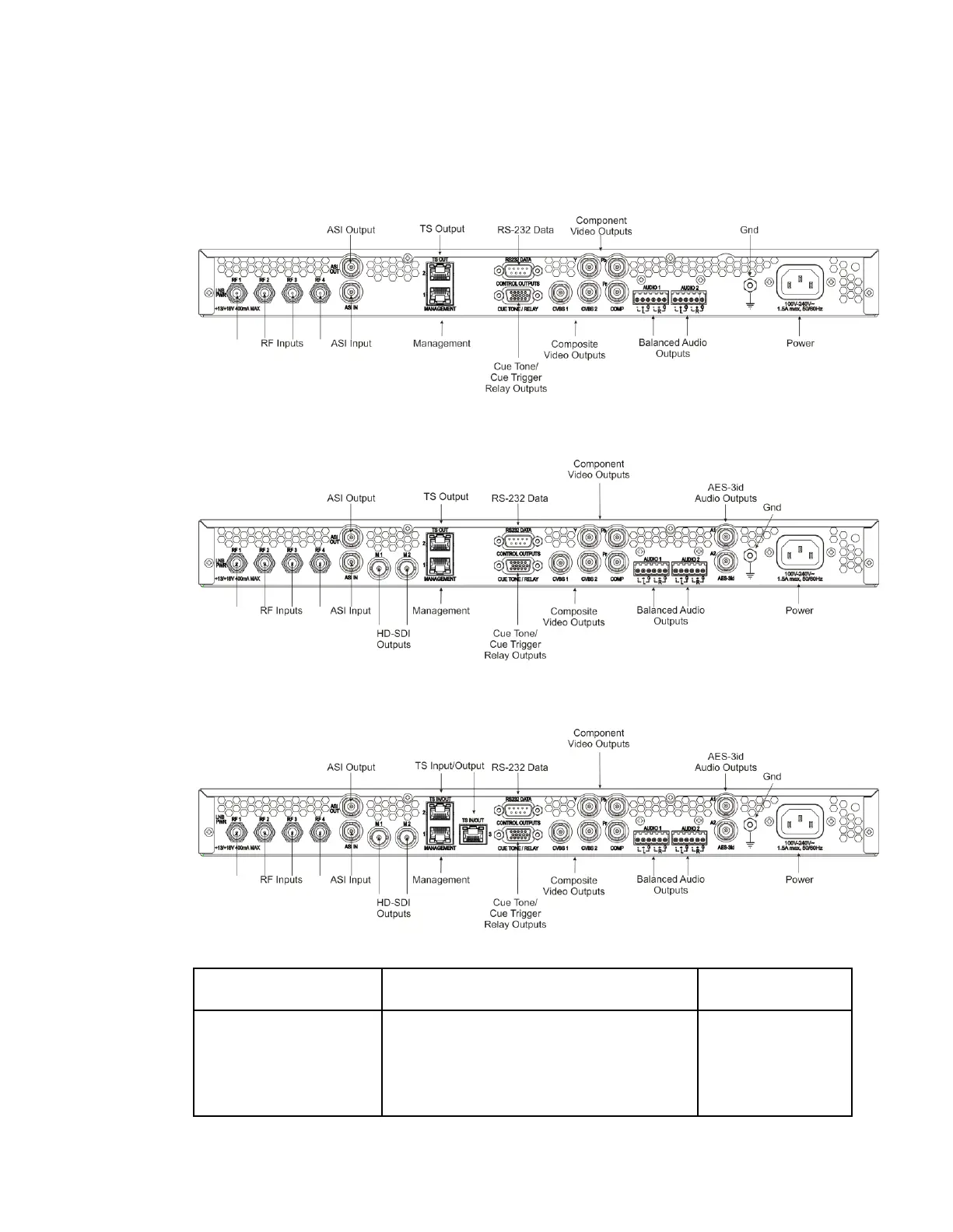
D9854/D9854-I Receiver Rear Connector Panel
The following diagrams show the rear connector panel of the D9854 base model:
The following displays the rear connector panel of the D9854, with SDI, SD/HD-SDI,
and AES outputs:
The following displays the rear connector panel of the D9854-I receiver, with SDI
and MPEGoIP Input:
The following table describes the function and type of the various connectors.
Connector
Description
Type
RF Inputs
Each input accepts an LNB signal input.
RF1 provides LNB power for use when no
external LNB power source is available. RF2
to RF4 require an external LNB power
source.
F

Table of Contents

Other manuals for Cisco D9854

Questions and Answers:

Question and Answer IconNeed help?

Do you have a question about the Cisco D9854 and is the answer not in the manual?

Cisco D9854 Specifications

General IconGeneral
ModelD9854
CategoryReceiver
OutputASI, IP
DecodingMPEG-2
Conditional AccessBISS
Receiver TypeProfessional IRD
解密DVB-CSA, BISS, AES
Input Frequency Range950 MHz to 2150 MHz
Modulation FormatsQPSK, 8PSK
Symbol Rate1 to 45 Msps
Power Supply100-240 VAC, 50/60 Hz
Power Consumption40W (typical)
Operating Temperature0°C

Related product manuals