User Manual Synertia® RF Generator VII
The information contained in this manual is subject to change by Comet Yxlon without prior notice.
Figure 30 Water Out and Water In properly connected ............................................................ 50
Figure 31: Wiring of mains connector air-cooled unit .................................................................. 54
Figure 32: Wiring of mains connector water-cooled unit ............................................................ 54
Figure 33: Mains connector air-cooled unit .................................................................................... 54
Figure 34: Mains connector water-cooled unit .............................................................................. 54
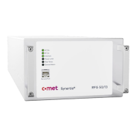
Figure 35: LEDs on the front panel of air- and water-cooled Synertia® RF generators ...... 59
Figure 36: Front view and rear view of the air-cooled Synertia® RF generator ...................... 71
Figure 37: Left side view of the air-cooled Synertia® RF generator .......................................... 71
Figure 38: Top view of the air-cooled Synertia® RF generator ................................................... 71
Figure 39: Right side view of the air-cooled Synertia® RF generator ....................................... 72
Figure 40: Front view and rear view of the water-cooled Synertia® RF generator .............. 73
Figure 41: Left side view of the water-cooled Synertia® RF generator .................................... 73
Figure 42: Top view of the water-cooled Synertia® RF generator ............................................ 73
Figure 43: Right side view of the water-cooled Synertia® RF generator ................................. 74
Figure 44: Interface configuration .................................................................................................... 75
Figure 45: Analog Input ...................................................................................................................... 80
Figure 46: Analog Output .................................................................................................................. 80
Figure 47: Digital Input ....................................................................................................................... 80
Figure 48: Digital Output .................................................................................................................. 80
Figure 49: Interlock ............................................................................................................................... 81
Figure 50: Serial Interface RS-232 ................................................................................................... 81
Figure 51: DC-Supply connector........................................................................................................ 84
Figure 52: Interlock connector ........................................................................................................... 85
Figure 53: Interlock ............................................................................................................................... 86