3.5 DS8110 CONNECTOR PANELS
After completing mechanical installation, use this section to properly wire your scanners for
optimal performance in your application. DS8110 wiring connections are made to the
connector panel and through the CBX connection box (connected to the I/O port of the
scanner). In most applications, the cable connections to the scanner will include:
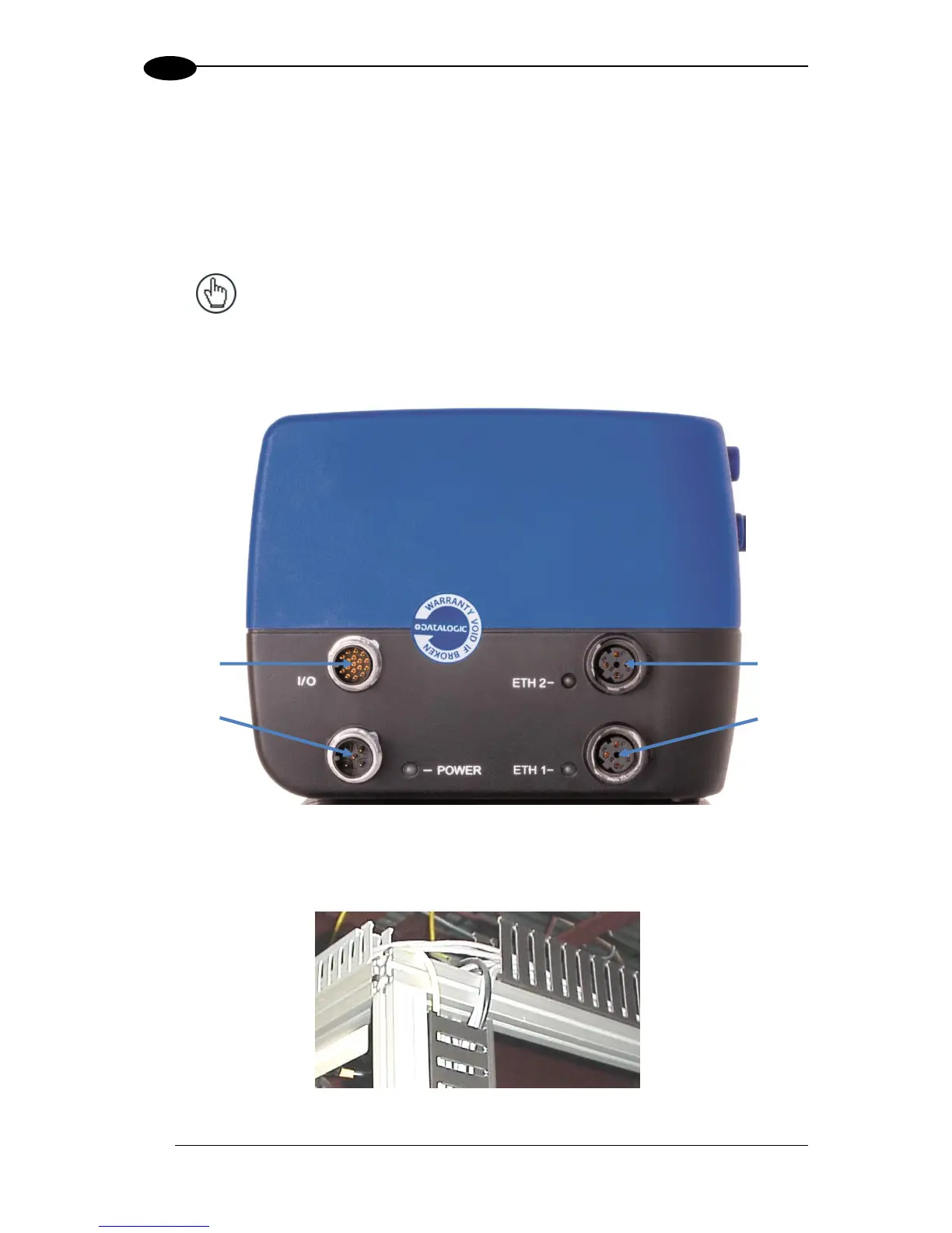
1. I/O (Connects directly to the 25-pin D type connector on the CBX connection box)
NOTE: The M12 I/O connector Vcc pin is allowed
a max sink current of 0.6A.
2. POWER
3. ETH 2 (Setup or EBC scanner network, default IP Address: 192.168.3.100)
4. ETH 1 (Host or EBC scanner network, default IP Address: 172.27.101.220)
Figure 26: DS8110 Connector Panel
Route wiring from the scanner’s connector panel through the wiring channels (if available) on
the Datalogic mounting structure when interconnecting cables to other devices.
Figure 27: Wiring Channels