BARCODE SCANNING FEATURES
5.6.3 Side-Mounted Barcode Scanner Calibration Using PackTrack
NOTE: It is not possible to illustrate every possible installation angle and
scanner mounting position in this manual. Use the following steps as a general
guide to calibrating each system scanner using barcodes in three positions. You
will need to make adjustments to the label/box position based on your situation.
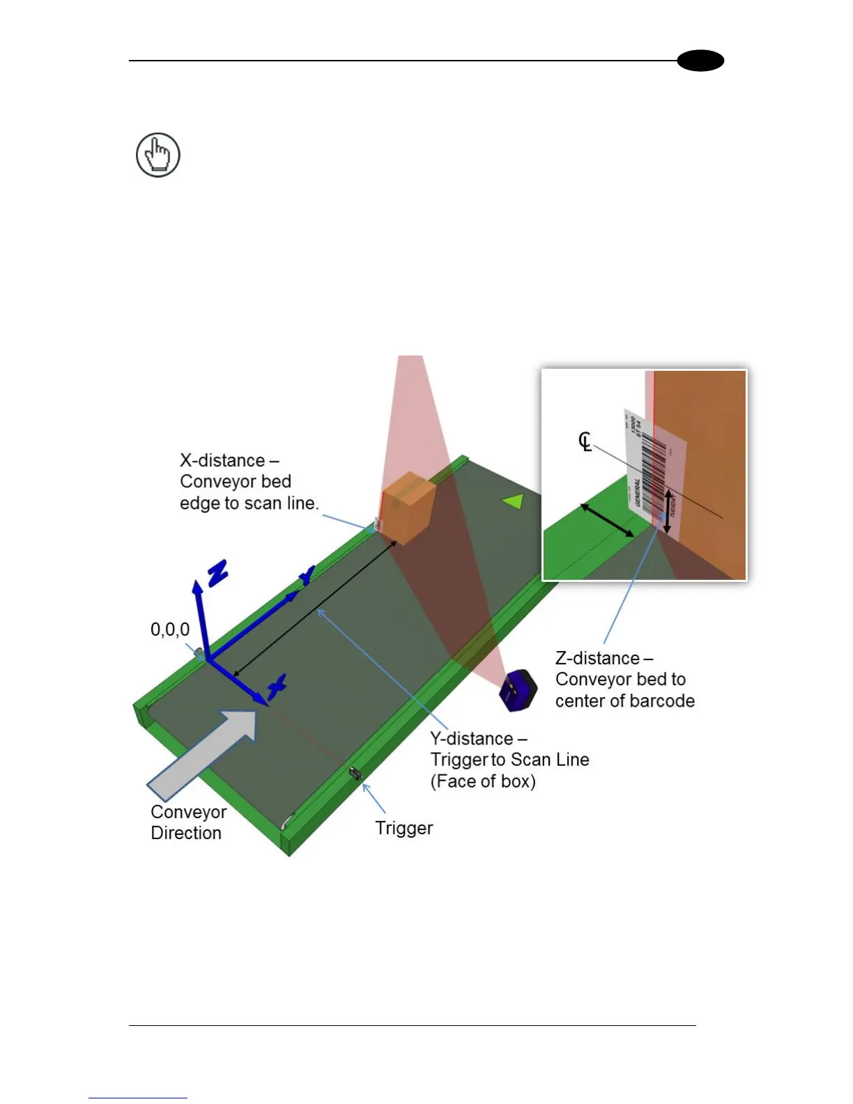
It is, however, important to note the fixed XYZ coordinates of the conveyor.
With the belt stopped, measure and enter the barcode XYZ coordinate data for each scanner
as follows:
1. Start by placing a system barcode hanging halfway past the back lower left edge of a
box, and then place the box along the edge of the conveyor belt as shown in the
illustration below.
Figure 54: Side-read 1
st
barcode placement
2. Measure the distance for X from the edge of the conveyor bed to the laser line centered
on the barcode, and enter that distance in the first box under X-Coord (mm) in the PackTrack
Calibration Wizard.
Your measurements will likely differ from those shown below.