3.7 POWER CONNECTOR PIN-OUT TABLE
A recommended power supply and cabling is available with the DS8110 and DX8210 (and
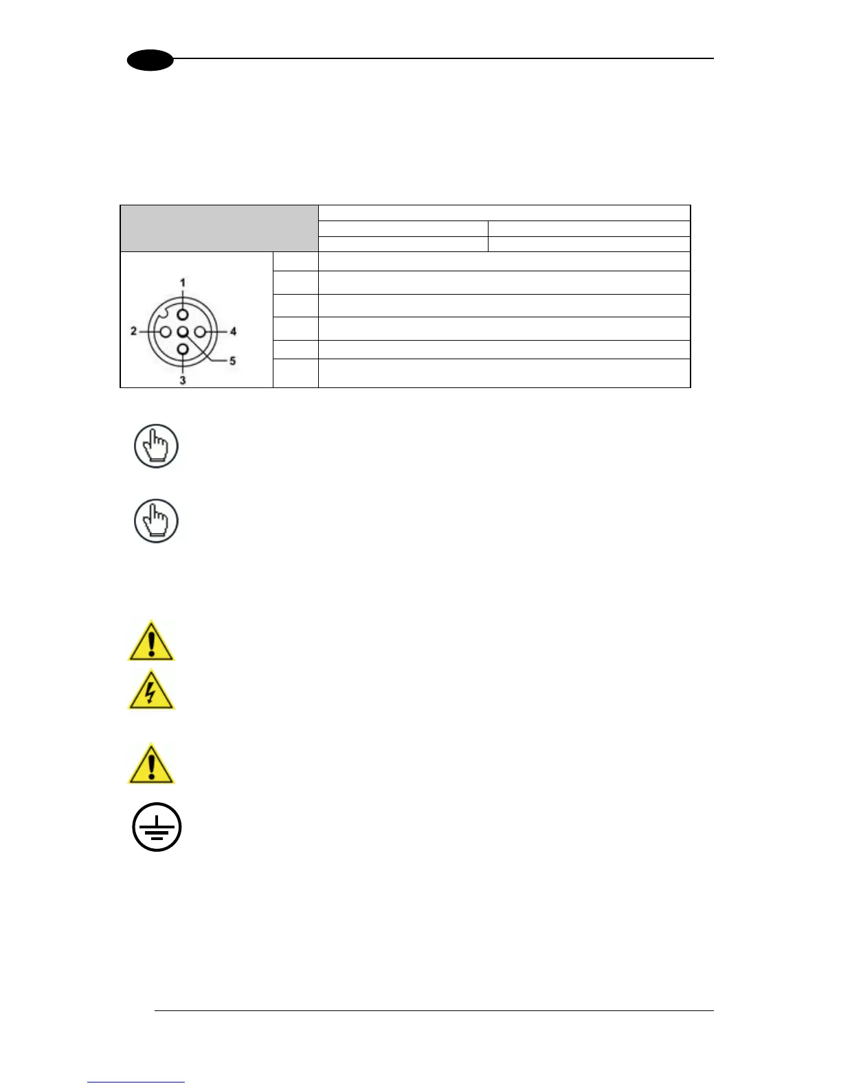
SC5000 Controller). However, if your installation requires custom power supply wiring, the
pin-outs of the unit power connector are provided below for your convenience.
NOTE: When using a DS8110 barcode scanner, no power supply is required
for the CBX510 connection box. All power and some communication options
are fed to the CBX510 through the scanner’s 17-pin I/O connector to the
CBX510 25-pin connector using the cable provided.
NOTE: In cases where the AS-I cabling is not used, the alternative CAB-LP-05
cable can be used to connect the power supply to the scanner. Connect the
Brown/White pair to +24 Vdc and the Blue/Black pair to 0 V- (GND).
IMPORTANT: When planning your installation wiring, remember all power
connections must be quick-disconnect.
CAUTION: While performing the following wiring connection procedures, be
sure to follow all safety procedures regarding high-voltage as outlined in the
Introduction to this manual. No power should be applied to any device until all
wiring is completed and checked for accuracy.
IMPORTANT: The socket-outlet must be installed near the scanner. The
outlet must be a readily accessible disconnect device.
GROUND: Ground the scanner to safety ground (protective earth ground
(PE)). See wiring recommendations for safety ground.
The CBX connection boxes provide flexible connectivity to a range of I/O devices as well as
serial hosting. The DS8110 connects to the CBX via its I/O port using a single 17-pin M12 to
25-pin D cable. The CBX connection box also provides space for an optional BM100 backup
module (recommended) for parameter storage, allowing quick replacement and configuration
of the scanners.
In a system with multiple scanners and other devices required in a scanning array (tunnel),
an SC5000 Controller serves as the system Master and provides communications between
protective earth (chassis)