Standard Cable Pinouts for DSM049X models
Product Reference Guide 233
Standard Cable Pinouts for DSM049X models
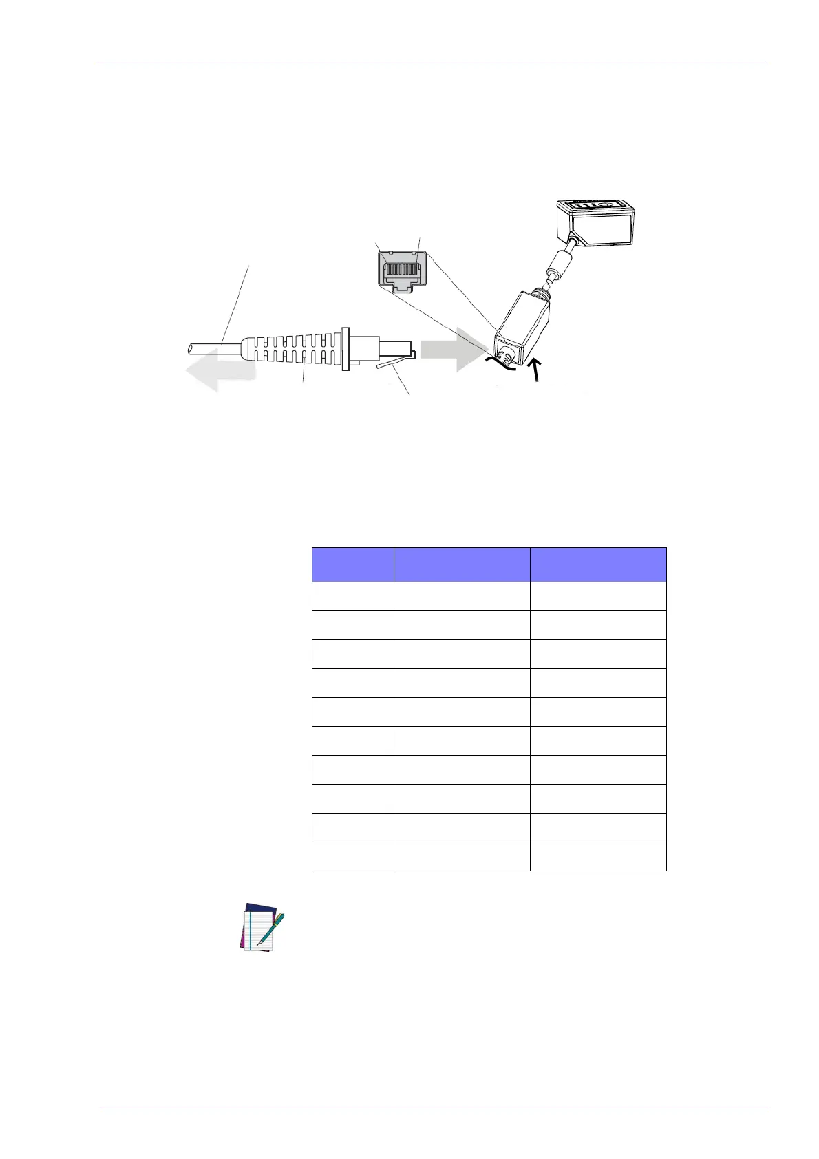
Figure 1 and
Table 1
provide standard pinout information for the scanner’s
cable.
Figure 1. Standard Cable Pinouts for DSM049X models
DSM049X Model
Cable clip (Latch)
Pin Hole on the bottom
side
Pin 1
Pin 10
Cable
To host
Cable Strain Relif
Interface Cable Port
The signal descriptions in
Table 1
apply to the connector on the scanner and are
for reference only.
Table 1.
Standard Cable Pinouts — Scanner Side
Pin RS-232 USB
1 RTS (out)
2 D+
3 D-
4 GND GND
5 RX
6 TX
7 VCC VCC
8
9
10 CTS (in)
NOTE
IMPORTANT: DSM049X has to be used
only with the Datalogic RS-232
or USB Cables indicated in the accessories list.