PASS-THROUGH
PRODUCT REFERENCE GUIDE
101
PASS-THROUGH
The pass-through layout allows each device working Alone, to collect data from one or
more pass-through input channels and send this data plus its own on one or more dif-
ferent
output channels.
In this way independent devices can be connected together in combinations to create
multi devi
ce networks. Many devices reading independently can send their messages
through a common output channel which instead of being directed at a Host can be col-
lected by another device on its pass-through input channel and sent to a Host on a dif-
ferent output channel.
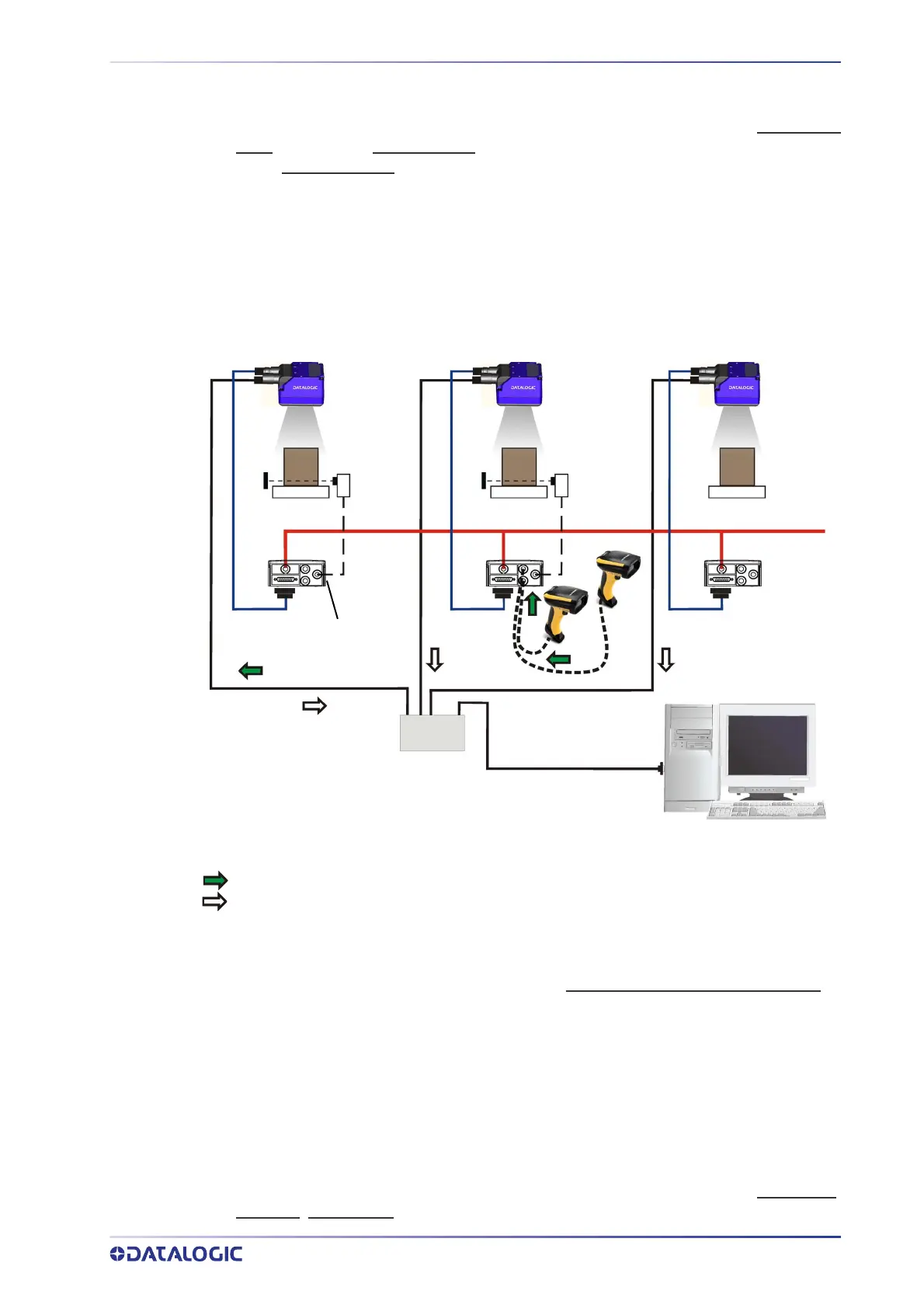
Host
CAB-DSxx-S
Phase
CAB-ETH-X-M0x
Ethernet TCP/IP Server 1
Ethernet TCP/IP Server 2
Main Serial Interface (RS232 or RS422 Full-Duplex)
Auxiliary Serial Interface (RS232)
Pass-through Input Channel
Output Channel
Alone
Alone Alone
CBX
Switch
Power
Mode
Continuous
Mode
External
Trigger
Figure 79 - Pass-Through Layout
In a Pass-through layout each device supports multiple pass-through configurations to
accept input from different devices on different channels (i.e. middle reader above). How-
ever, readers are not required to have a pass-through configuration if they don’t need to
receiv
e data from an input channel (i.e. right reader above). The overall data collection
device always has at least one pass-through configuration to collect the input data from
the other devices and send it to the Host (i.e. left reader above).
All devices always support multiple output channels (i.e. for data monitoring).
In a Pass-through layout each device can have a different operating mode:
Continuous,
One Shot, Phase Mode, etc.