PRODUCT REFERENCE GUIDE
183
APPENDIX B
ALTERNATIVE CONNECTIONS
The connector pinouts and notes given in this appendix are for custom cabling applica-
tions.
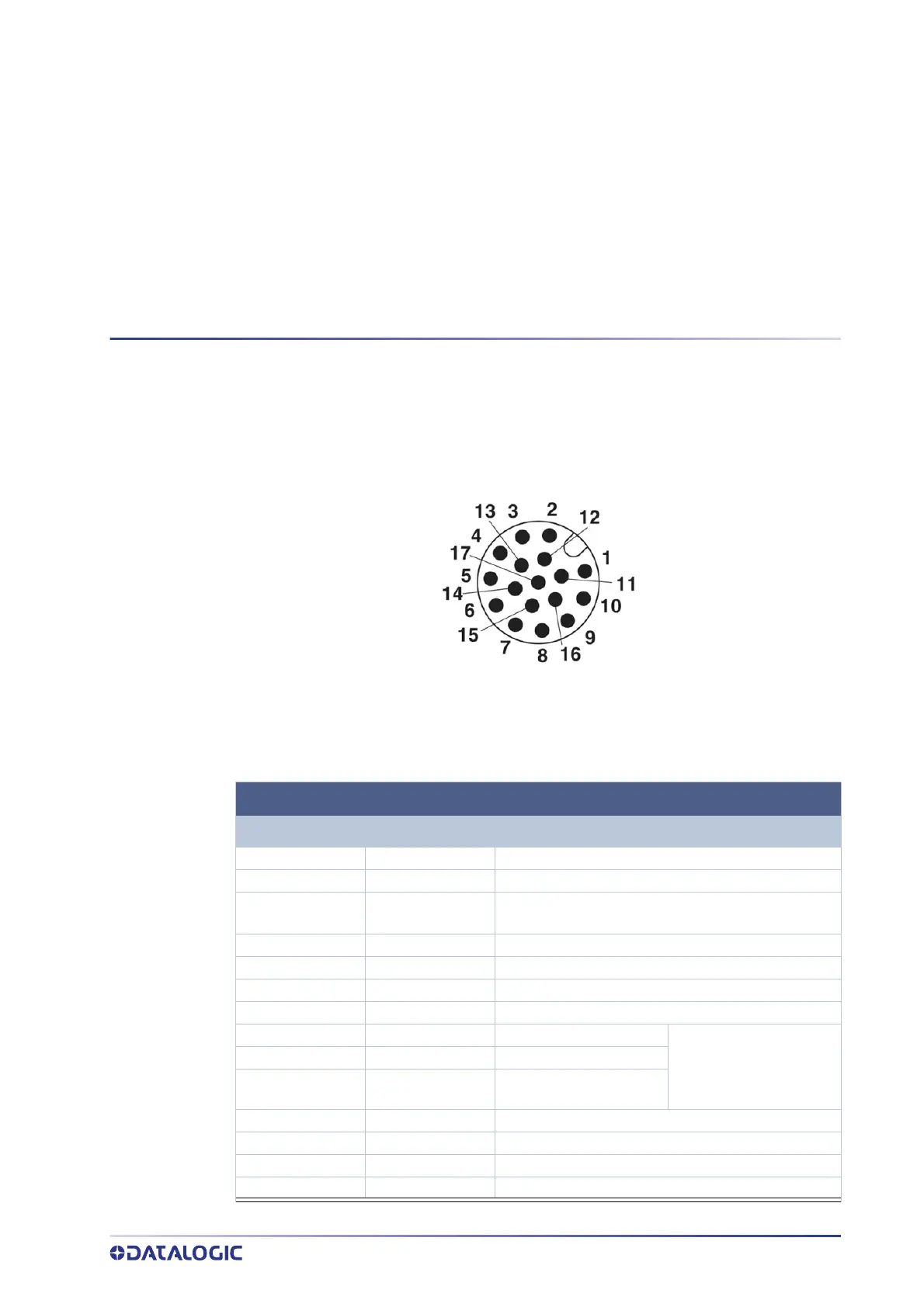
POWER, COM AND I/O CONNECTOR FOR STANDARD MODELS
Figure 1 - M12 17-pin male Power, COM and I/O Connector
POWER, COM AND I/O CONNECTOR PINOUT
PIN NAME DESCRIPTION
1 Vdc Power supply input voltage +
2 GND Power supply input voltage -
Connector case CHASSIS
Connector case provides electrical connection to
the chassis
6 I1A External Trigger A (polarity insensitive)
5 I1B External Trigger B (polarity insensitive)
13 I2A Input 2 A (polarity insensitive)
3 I2B Input 2 B (polarity insensitive)
9 O1 Output 1 (NPN or PNP short cir-
cuit protected
and software program-
mable)
8 O2 Output 2
16 O3 Output 3
14 RX Auxiliary RS232 RX
4 TX Auxiliary RS232 TX
7 ID+ ID-NET network data +
15 ID- ID-NET network data -