MAIN SERIAL INTERFACE
PRODUCT REFERENCE GUIDE
73
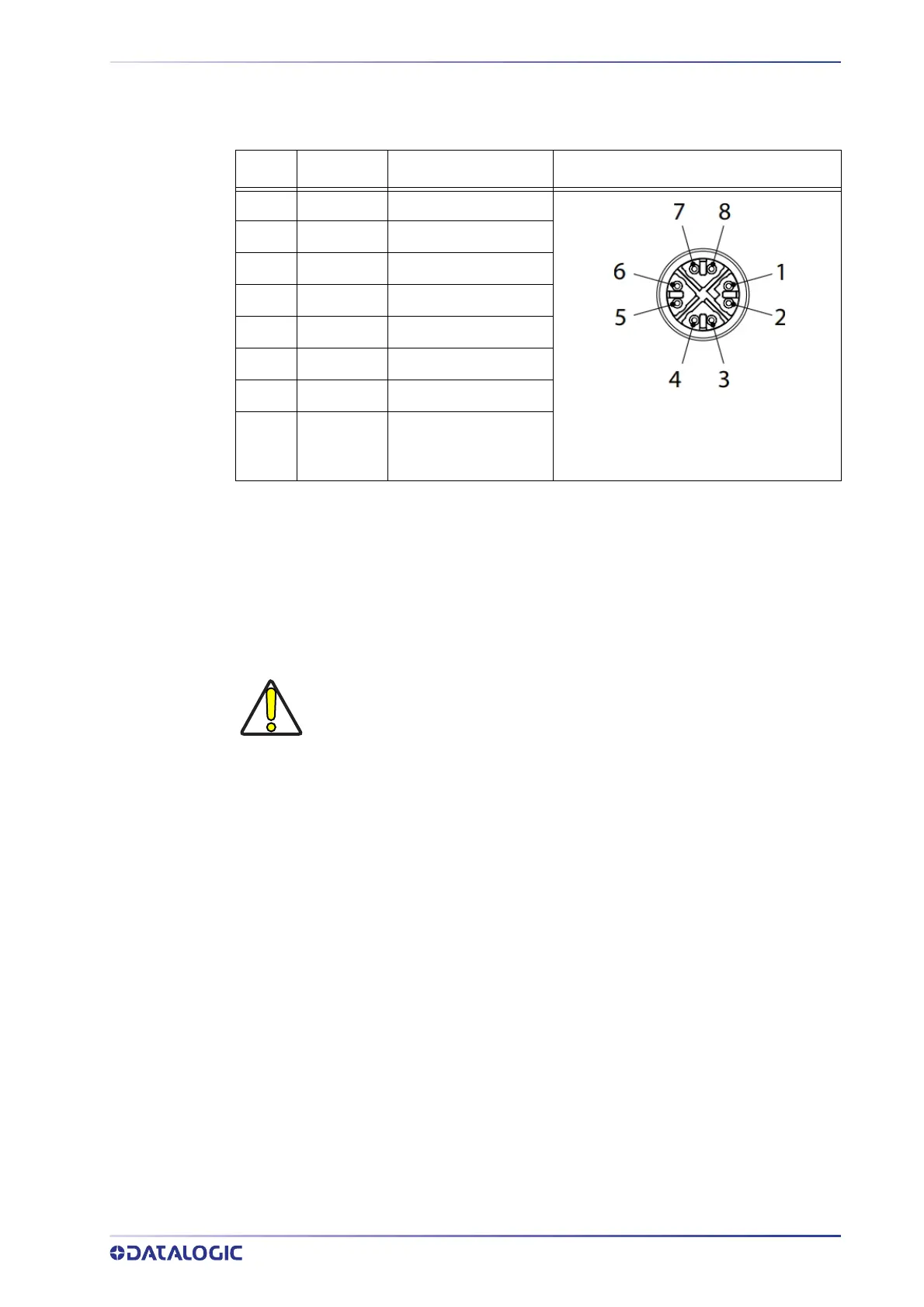
Power Over Ethernet (PoE) Models
The Ethernet pinout is as follows:
Pin Name Description
1 TX+ Transmit data +
Figure 47 - M12 X-Coded Female
Ethernet Network Connector
2 TX- Transmit data -
3 RX+ Receive data +
4 RX- Receive data -
5 DC1- DC power (-)
6 DC2- DC power (-)
7 DC1+ DC power (+)
8 DC2+ DC power (+)
Power can be applied to any of the data pairs according to the IEEE 802.3af standard for
Alternative A (Mid and Endspan) or Alternative B.
MAIN SERIAL INTERFACE
The signals relative to the following serial interface types are available on the CBX spring
clamp terminal blocks.
The main serial interface type and its parameters (baud rate, data bits, etc.) can be
defined by
the user via DL.CODE software. For more details refer to the Help On Line
page of the Reading Phase step (Channels) in DL.CODE.
Details regarding the connections and use of the interfaces are given in the next para-
graphs.
CAUTION
Do not connect to the Main Interface spring clamp terminals if using Host
Interface Modules (Fieldbus) with the CBX500.