ID-NET SYNCHRONIZED NETWORK
PRODUCT REFERENCE GUIDE
103
All devices always support multiple output channels (i.e. for data monitoring).
In a Pass-through layout each device can have a different operating mode: Continuous,
One Shot, Phase Mode, etc.
ID-NET SYNCHRONIZED NETWORK
When the device is working Synchronized, the ID-NET connection is used to collect data
from several readers to build a multi-point or a multi-sided reading system; there can be
one Master and up to 31 Slaves connected together.
The Slave readers are connected together using the ID-NET interface. Every slave reader
must
have an ID-NET address in the range 1-31.
The Master reader is also connected to the Hos
t on o
ne of its communication channels.
In the following examples the RS232/RS422 main serial interface is used.
For a Master/Slave Synchronized layout the External Trigger signal is unique to the sys-
tem; there is a single reading phase and a single message from the Master reader to the
Hos
t c
omputer. It is not necessary to bring the External Trigger signal to all the read-
ers.
In the Master/Slave Synchronized layout the Master operating mode can only be set to
PackTrack or Phase Mode.
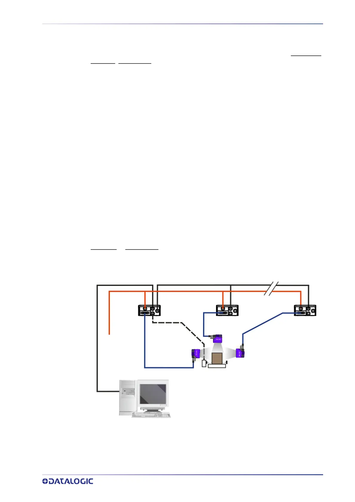
The Main and ID-NET interfaces are connected as shown in the following figures.
Host
Power
ID-NET
Master
Synchronized
ID-NET
Slave#1
Synchronized
ID-NET
Slave#n
Synchronized
Main Serial Interface (RS232 or RS422 Full-Duplex)
External Trigger
ID-NET (up to 16 devices - practical limit)
Figure 81 - ID-NET Synchronized Layout
The Master reader can be connected to the CBX series connection box with the advan-
tage of the Backup and Restore configurat
ion function (CBX + BM100 module).