Figure 100. Installing the NVMe-backplane assembly (optional)
Steps
1. Slide and insert the single NVMe-backplane assembly along with the NVMe cable, SATA power cable, fan cable, and
thermal-sensor cable into its slot on the chassis.
2. Using a Phillips screwdriver, tighten the two (M3) screws to secure the NVMe-backplane assembly to the chassis.
3. Route the SATA power, fan cable, and thermal-sensor cable through the routing guides on the chassis.
4. Open the lid of the bottom-air shroud cover to route the cables inside.
NOTE: Ensure to route all cables within the bottom-air shroud cover to avoid damage to the cables.
5. Connect the SATA power, fan cable and thermal-sensor cable to its connector on the system board.
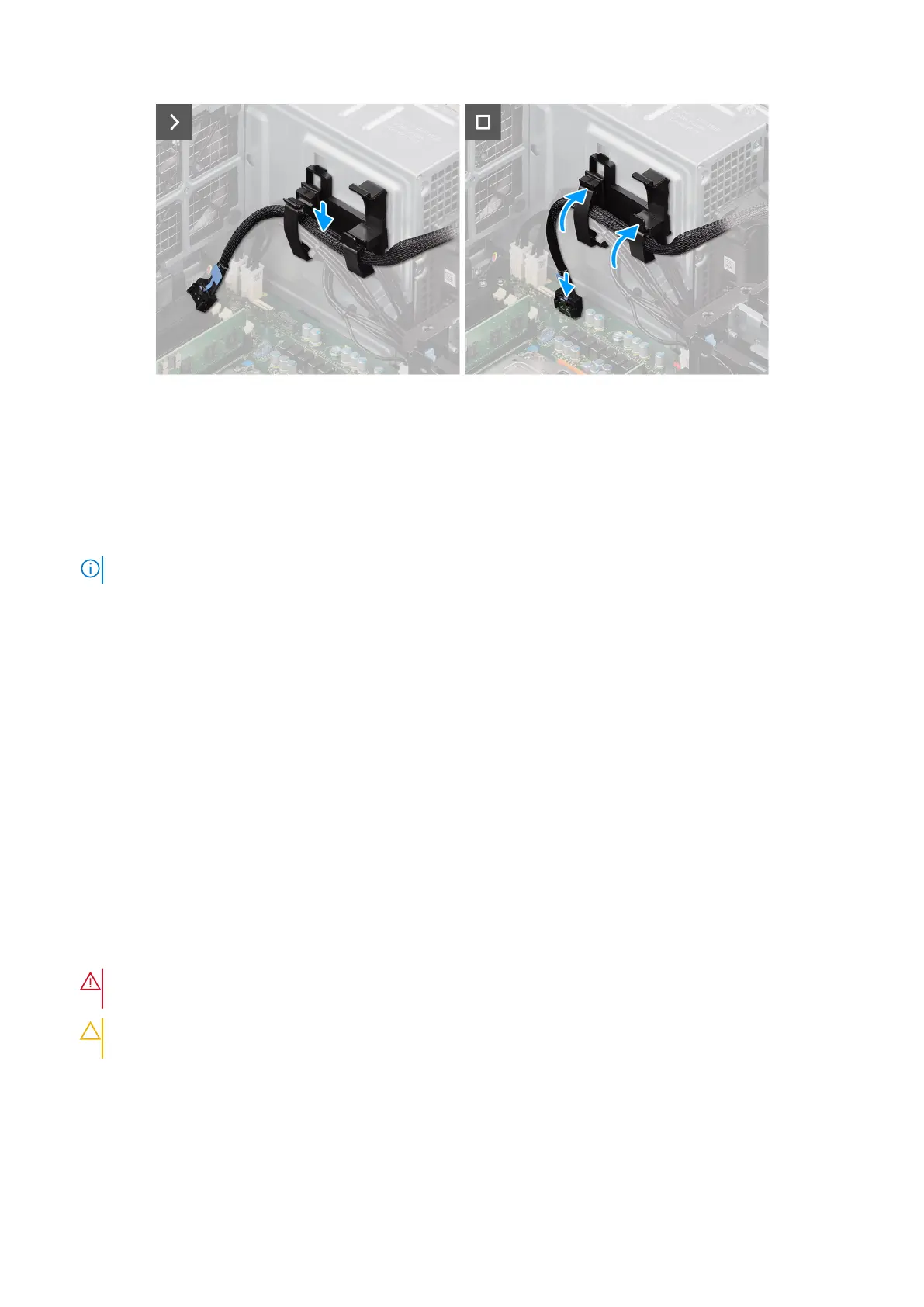
6. Open the plastic clips on cable holder.
7. Route the NVMe cable through the plastic clips and close the plastic clips.
8. Connect the NVMe cable to its connector on the system board.
Next steps
1. Install the air shroud.
2. Install the side cover.
3. Follow the procedure in After working inside your computer.
Heat sink
Removing the heat-sink assembly
Prerequisites
1. Follow the procedure in Before working inside your computer.
WARNING:
The heat sink may become hot during normal operation. Allow sufficient time for the heat sink to
cool before you touch it.
CAUTION: For maximum cooling of the processor, do not touch the heat transfer areas on the heat sink. The
oils in your skin can reduce the heat transfer capability of the thermal grease.
2. Remove the side cover.
3. Remove the air shroud.
About this task
The following images indicate the location of the heat-sink assembly and provide a visual representation of the removal
procedure.
128
Removing and installing Field Replaceable Units (FRUs)