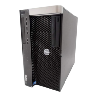
NOTE: The image of the heat-sink assembly may vary depending on the configuration ordered.
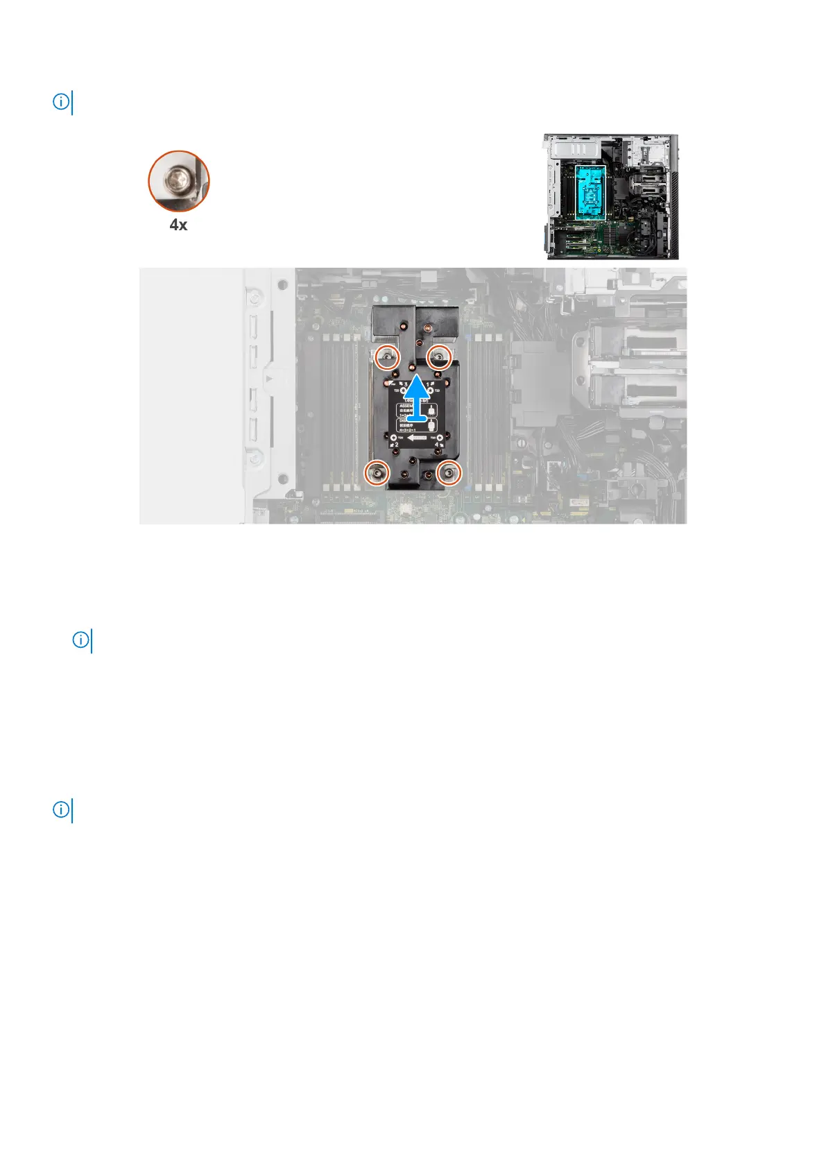
Figure 101. Removing the heat-sink assembly
Steps
1. Using a Torx T20 screwdriver, in reverse sequential order (4->3->2->1), loosen the four captive screws that secure the
heat-sink assembly to the system board.
NOTE:
2. Lift and remove the heat-sink assembly away from the computer.
Installing the heat-sink assembly
Prerequisites
If you are replacing a component, remove the existing component before performing the installation procedure.
NOTE: See the instructions that are provided with the kit for steps on how to apply the thermal grease.
About this task
The following images indicate the location of the heat-sink assembly and provide a visual representation of the installation
procedure.
Removing and installing Field Replaceable Units (FRUs)
129