3. Route the PCIe power-cables and SATA power-cables through the routing guides.
4. Connect the PCIe power-cables to the slots on the PCIe holder.
5. Connect the SATA power-cables to the ATX SYS connector on the system board.
NOTE: The location of the connectors on the system-board is described in System-board callouts.
6. Align and place the power-supply cover over the power-supply unit.
7. Install the two (#6-32) screws to secure the power-supply cover to the chassis.
8. Open the clips on the routing guides on the power-supply cover and route the CPU ATX power-cables through the clips.
9. Close the clips on the routing guides on the power-supply cover.
10.
● For 1000 W PSU: Connect two of the 4-pin ATX CPU power cables to the ATX CPU1 and ATX CPU2 connectors on the
system board.
NOTE: Insert the two six-pin PSU power cables (for graphics card) into the supplied PSU-cable holder.
● For 1350 W PSU: Connect three of the 4-pin ATX CPU power cables to the ATX CPU1, ATX CPU2 and ATX CPU3
connectors on the system board.
Next steps
1. Install the air shroud.
2. Install the side cover.
3. Follow the procedure in After working inside your computer.
System board
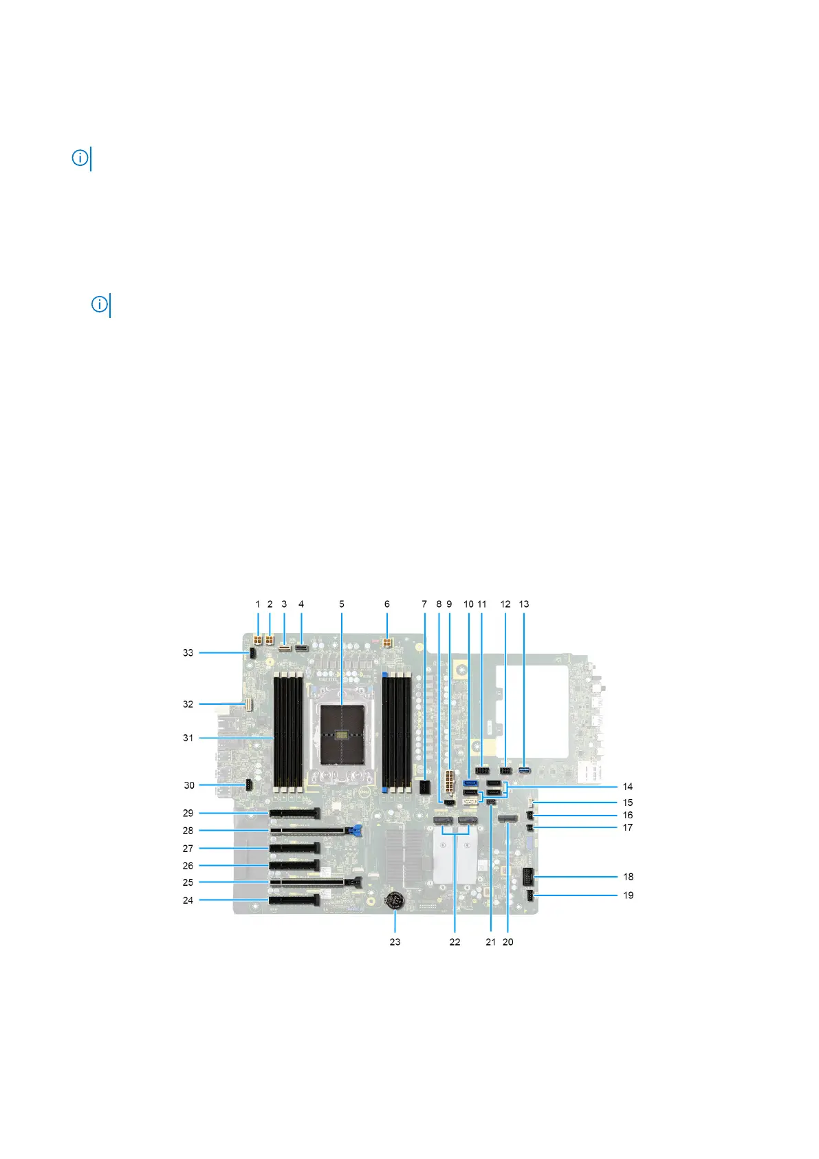
System-board callouts
This topic provides detailed callouts for the connectors on the system board:
Figure 117. System-board callouts
Removing and installing Field Replaceable Units (FRUs)
143