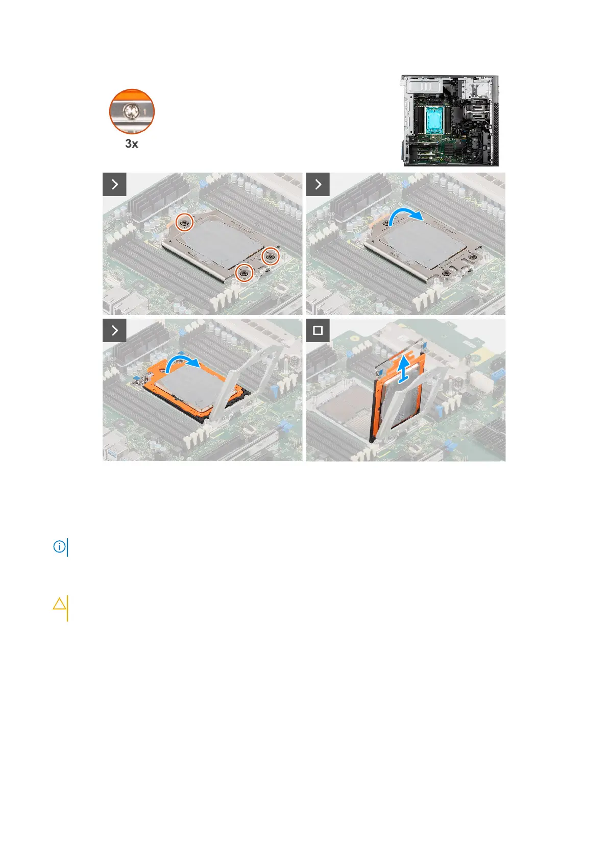
Figure 103. Removing the processor
Steps
1. Using a Torx T20 screwdriver, in reverse sequential order (3->2->1), loosen the three captive screws that secure the force
frame to the system board.
NOTE: The numbering and order in which to loosen the screws is printed on the force frame.
2. Lift and open the force frame.
3. Lift the CPU carrier by holding the two blue latch points on the rail frame and rotating it to the vertical position.
CAUTION:
When removing the processor, do not touch any of the pins inside the socket or allow any objects
to fall on the pins in the socket.
4. Gently slide the processor out of the CPU carrier.
Installing the processor
Prerequisites
If you are replacing a component, remove the existing component before performing the installation procedure.
About this task
The following images indicate the location of the processor and provide a visual representation of the installation procedure.
Removing and installing Field Replaceable Units (FRUs)
131