2. Open the plastic clips on cable holder.
3. Unroute the NVMe cable through the plastic clips and close the plastic clips.
4. Disconnect the SATA power, fan cable, and thermal-sensor cable from its connector on the system board.
5. Open the lid of the bottom-air shroud cover to unroute the cables from inside.
6. Unroute the SATA power, fan cable, and thermal-sensor cable from the routing guides on the chassis.
7. Using a Phillips screwdriver, loosen the two (M3) screws that secure the NVMe-backplane assembly to the chassis.
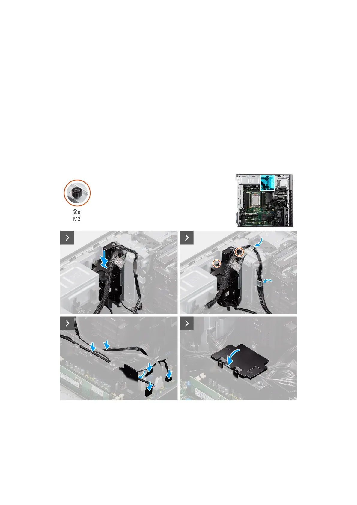
Installing the NVMe-backplane assembly (optional)
Prerequisites
If you are replacing a component, remove the existing component before performing the installation procedure.
About this task
The following images indicate the location of the NVMe-backplane assembly and provide a visual representation of the
installation procedure.
Figure 99. Installing the NVMe-backplane assembly (optional)
Removing and installing Field Replaceable Units (FRUs)
127