Patient Monitor User Manual Monitoring ECG
- 88 -
field density exceeding 3 v/m may cause measurement error in various frequencies. It
is accordingly suggested that do not use equipment generating electrical radiation
near ECG/RESP monitoring devices.
3 If the pacemaker signals are beyond the claimed range, the heart rate may be
calculated incorrectly.
4 In the default settings of the monitor, the ECG waveforms are the first two waveforms
from top in the waveform area.
5 For measurements in or near the heart we recommend connecting the monitor to the
potential equalization system.
6 For protecting environment, the used electrodes must be recycled or disposed of
properly.
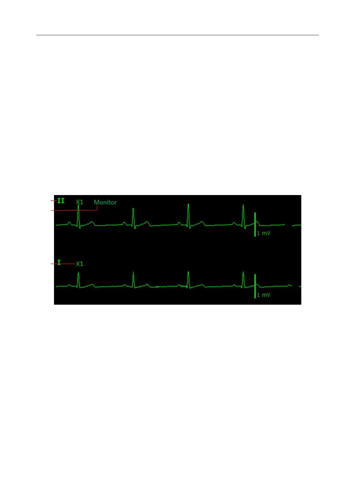
8.3 ECG Display
The figure below is for reference only.
The symbol ① indicates lead name of display waveform: there are several options, such as I, II,
III, aVR, aVF, aVL, V (for 5 leads). If you want to change the lead, please refer to section
Selecting Calculation Lead.
The symbol ② indicates waveform gain: there are several options, such as X0.125, X0.25, X0.5,
X1, X2, X4 and AUTO. If you want to change it, please refer to section Changing the Size of the
ECG Wave.
The symbol ③ indicates Filter setting, there are three options: Monitor, Surgery and Diagnosis.
If you want to change it, please refer to section Changing the ECG Filter Setting.
8.3.1 Changing the Size of the ECG Wave
If any of the displayed ECG waveform is too small or clipped, you can change the size of it on
the screen. First select ECG Waveform Setup > ECG Gain, then select an appropriate factor
from the pop-up box to adjust the ECG waveform.
X0.125: make size of ECG signal waveform of 1mV become 1.25 mm;
①
③
②