Patient Monitor User Manual Basic Operation
- 33 -
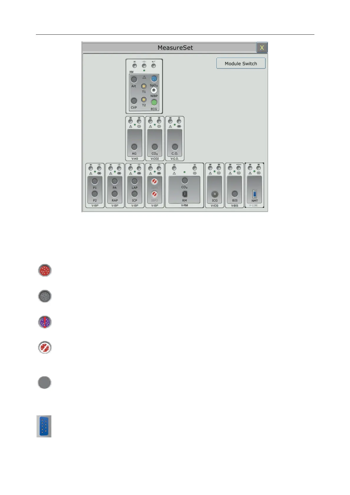
This menu displays the measurement modules which have been mounted in the XM module slot,
three-slot module rack and PAM from top to bottom. Beside each measurement connector is the
measurement label. The color in which a measurement connector appears matches the status of
the measurement parameter.
Colored: indicates the module is activated.
Grey: indicates the module is deactivated.
Colored with a “!” appearing: indicates a module conflict.
For IBP connectors, with a circle-slash symbol appearing: indicates an IBP module
conflict.
For IBP connectors in the XM module: indicates this XM module is not configured with
an IBP module.
Colored: indicates the module is activated.
 Loading...