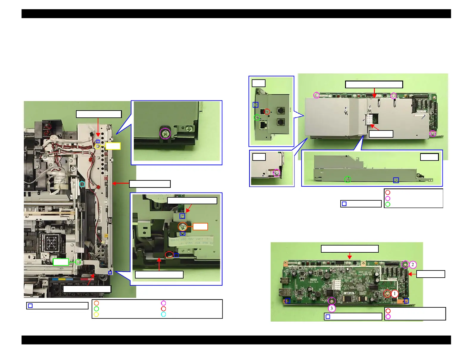
EasyManua.ls Logo

Epson Stylus Photo TX800FW

Epson Stylus Photo TX800FW
277 pages
To Next Page IconTo Next Page
To Previous Page IconTo Previous Page
Loading...
Revision C
DISASSEMBLY/ASSEMBLY
Disassembly Procedures
https://www.manualsbooks.com
118
Confidential
2.
Remove the screw (x1) that secures the Right Cable Frame and the Main
Board. (See Fig. 4-40.)
3.
Remove the screw (x1) that secures the Ferrite Core Holder A, and remove
the Ferrite Core Holder A. (See Fig. 4-40.)
4.
Remove the screw (x1) that secures the Grounding Plate M/B, and remove the
Grounding Plate M/B. (See Fig. 4-40.)
5.
Remove the screws (x3) that secure the Main Board Unit and remove the
Main Board Unit.
Figure 4-40. Removing the Main Board Unit
Main Board
1.
Disconnect the I/F-B FFC from the FAX board. (Artisan 800/PX800FW/
TX800FW only) (See Fig. 4-41.)
2.
Remove the screws (x7) that secure the Upper Shield Plate M/B, and remove
the Upper Shield Plate M/B.
Figure 4-41. Removing the Main Board (1)
3.
Remove the screws (x3) that secure the Main Board and remove the Main
Board from the Lower Shield Plate M/B.
Figure 4-42. Removing the Main Board (2)
C.B.S.(P2) 3x8 (8±1Kgfcm)
C.B.S. 3x6 (8±1Kgfcm)
C.B.S. 3x6 (6±1Kgfcm)
C.B.S. 3x6 (5±0.5Kgfcm)
C.B.P. 3x8 (6±1Kgfcm)
C.B.P. 3x10 (6±1Kgfcm)
Step 4
Step 3
Main Board Unit
Step 2
Right Cable Frame
Positioning hole & dowel
Grounding Plate M/B
Ferrite Core Holder A
Holder IC Shield Plate
Upper Shield Plate M/B
Bottom
Rear
I/F-B FFC
Rear
Dowel & groove
C.P. 3x6 (4±1Kgfcm)
C.B.S. 3x6 (4±1Kgfcm)
C.B.S. 3x6 (8±1Kgfcm)
Positioning hole & dowel
C.B.S. 3x10 (8±1Kgfcm)
C.B.S. 3x6 (8±1Kgfcm)
Main Board
Lower Shield Plate M/B

Table of Contents

Other manuals for Epson Stylus Photo TX800FW

Related product manuals