Epson Artisan 800/Epson Stylus Photo PX800FW/TX800FW/Epson Artisan 700/Epson Stylus Photo PX700W/TX700W
Disassembly Procedures
https://www.manualsbooks.com
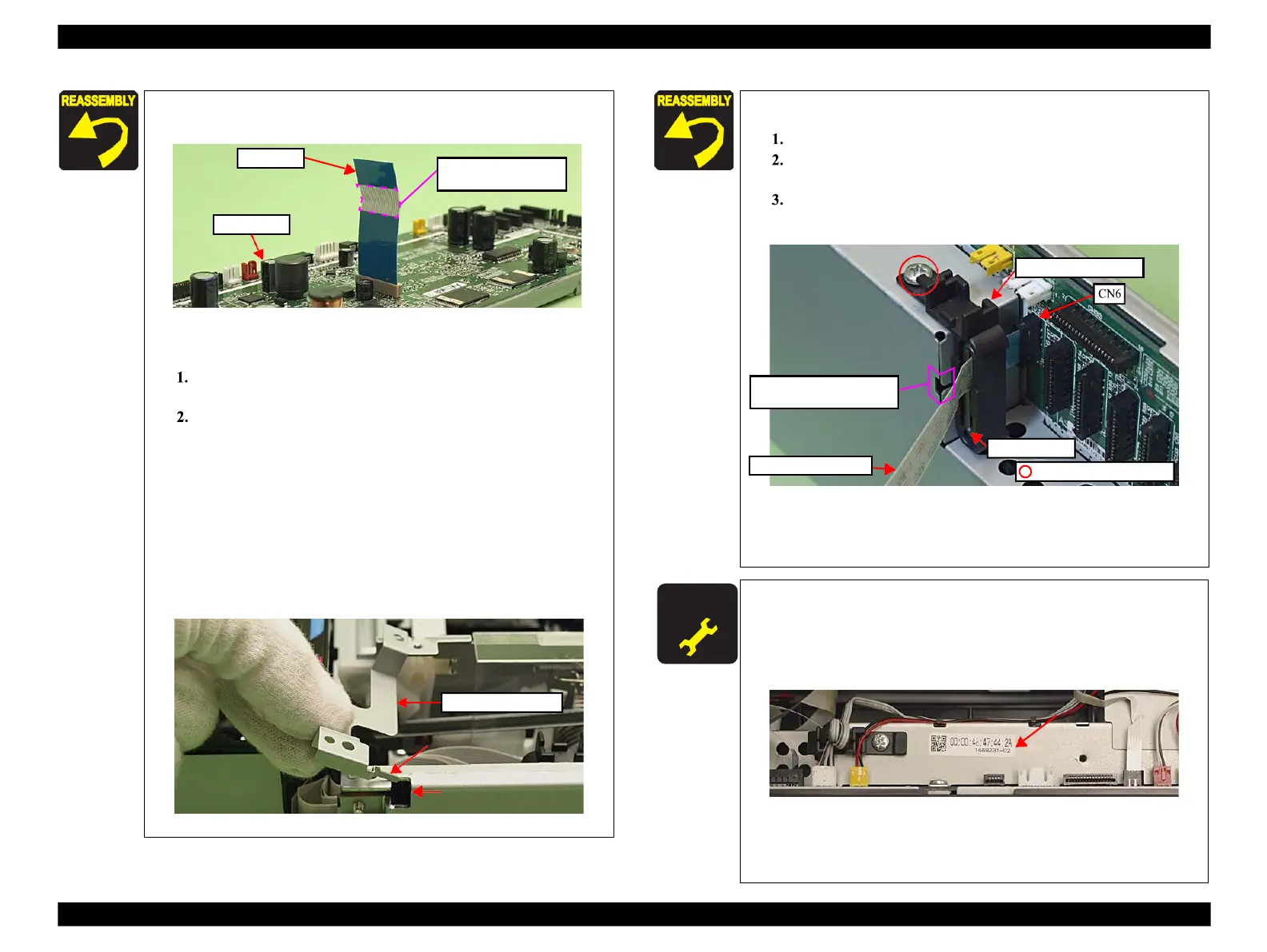
When connecting the I/F-B FFC to the Main Board, connect it
Figure 4-45. Connecting the I/F-B FFC
Attach the Ferrite Core Holder A as follows.
Align the dowels (x2) of the Main Board Unit with the
positioning holes (x2) of the Holder IC Shield Plate.
Secure the Ferrite Core Holder A and the Holder IC Shield
Plate to the Main Board Unit with the screw. (See Fig.
4-40.)
Align the dowel (x1) of the Main Board Unit with the
positioning hole (x1) of the Right Cable Frame. (See Fig. 4-40
.)
Insert the rib (x1) of the Grounding Plate M/B to the hole of the
Main Board Unit, and align the positioning hole (x1) of the
Grounding Plate M/B with the dowel (x1) of the Main Board
Unit, and attach the Grounding Plate M/B. (See Fig. 4-40, Fig.
4-46.)
Figure 4-46. Attaching the Grounding Plate M/B
Attach this part to the
FAX Board side.
When replacing the Main Board, the MAC address need to be
set if the EEPROM data could not be read from the old Main
Board. In this case, attach the new “ Label, MAC address (Parts
number: 1489231)” to the position shown in Fig. 4-48 and
execute “ 5.2.6 "MAC Address Setting" (p223)”.
Figure 4-48. Position for the MAC Address Label
After removing/replacing the Main Board, make the specified
adjustments. (See Chapter 5 "ADJUSTMENT".)
When attaching the CR Encoder FFC, follow the procedure
below.
Put the CR Encoder FFC through the ferrite core.
Connect the CR Encoder FFC to the connector (CN6) on
the Main Board.
Insert the rib of the Ferrite Core Holder B to the hole of the
Main Board, and secure it with the screw (x1).
Ferrite core
C.B.S. 3x6 (5±0.5Kgfcm)
Figure 4-47. Attaching the CR Encoder FFC
For routing cables and FFCs, see 4.4 "Routing FFC/cables"
Align and insert the rib of
the Ferrite Core Holder B
 Loading...


