Parts/Components need to be removed in advance:
ADF Unit (Artisan 800/PX800FW/TX800FW only)/Scanner Unit/Upper Left
Housing/Paper Guide Top Assy/Upper Housing
Removal procedure
1.
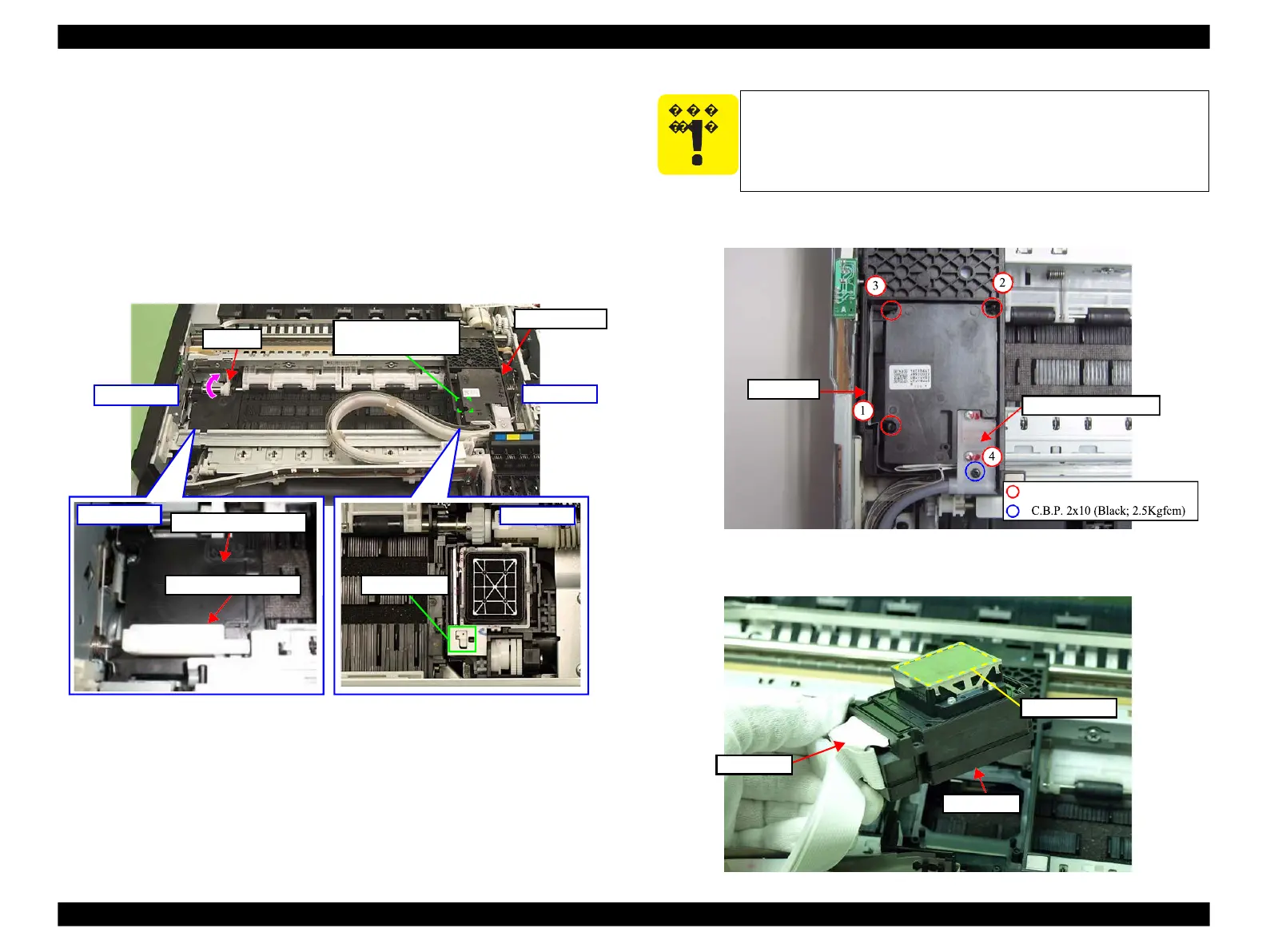
Place the Carriage stopper jig on 80-digit side on the Paper Guide Front Assy.
2.
Turn the Spur Gear in the direction of the arrow, and release the Carriage
Lock. (See Fig. 4-57.)
3.
Move the Carriage Unit to the 80-digit side, and place it on the Carriage
stopper jig.
Figure 4-57. Releasing the Carriage lock and placing the Carriage stopper jig
4.
Remove the screws (x4) that secure the Printhead and the Ink Supply Tube
Assy, and detach the Printhead from the Carriage Unit.
Figure 4-58. Removing the Printhead (1)
5.
Disconnect the Head FFC (x2) from the Printhead.
Figure 4-59. Removing the Printhead (2)
damage the nozzle plate surface of the head. (See Fig. 4-59.)
Do not damage or contaminate the CR Seal, or touch it with
bare hands either. (See Fig. 4-62.)
 Loading...


