Epson Artisan 800/Epson Stylus Photo PX800FW/TX800FW/Epson Artisan 700/Epson Stylus Photo PX700W/TX700W
Disassembly Procedures
https://www.manualsbooks.com
ASSEMBLING THE PRINTHEAD
6.
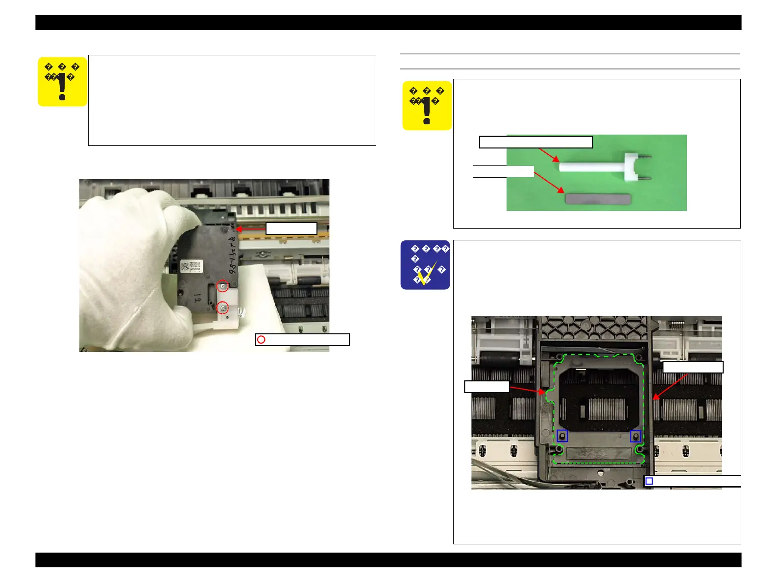
Remove the screws (x2) that secure the Ink Supply Tube Assy and remove the
Ink Supply Tube Assy from the Printhead, then remove the Printhead.
Figure 4-60. Removing the Printhead (3)
In the next steps, make sure to take measures against
contamination of the surroundings from ink such as receiving it
with BEMCOT or the like.
Using a piece of clean BEMCOT or the like, wipe off the leaked
ink when removing the Printhead.
Make sure not to touch the joint point of the Printhead and the
Ink Supply Tube Assy. (See Fig. 4-60.)
When assembling the Printhead, make sure to use the Ink Supply
Tube screwing tool following the procedure in this section in order
to avoid spilling ink from the joint of the Ink Supply Tube Assy and
the Printhead.
Ink Supply Tube screwing tool
Figure 4-61. Ink Supply Tube screwing tool
When installing the Printhead, confirm the CR Seal is not
folded or out of position, then install it without any gap in
between.
When the CR Seal gets out of position, make sure to align the
positioning holes (x2) of it with the dowels (x2) on the Carriage
Unit, then install it without any gap.
Carriage Unit
CR Seal
Figure 4-62. Installing the CR Seal
When installing the Printhead, make sure to move the Carriage
to the 80-digit side and place it on the Carriage stopper jig in
order to prevent the frame from deforming.
 Loading...


