Epson Artisan 800/Epson Stylus Photo PX800FW/TX800FW/Epson Artisan 700/Epson Stylus Photo PX700W/TX700W
Disassembly Procedures
https://www.manualsbooks.com
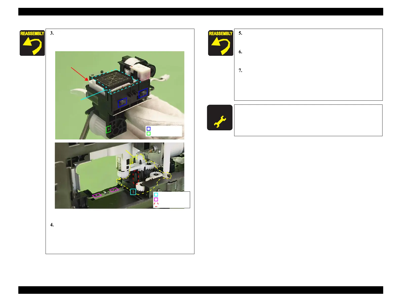
Align the dowels (x2) and the positioning hole (x1) of the Ink
System with the positioning holes (x2) on the Main Frame and the
dowel (x1) on the Transmission Holder Assy shown in Fig. 4-87
Figure 4-87. Installing the Ink System (3)
Align the dowel of the Ink System with the positioning hole on the
Main Frame, and secure it with the screw (x1) to the Ink
System.(See Fig. 4-83.)
(Continued to the next page.)
Rubber Seal,
Head Cleaner
Push the switch lever in the direction of the arrow and turn the
.), then align the Transmission Arm to the
position A (Ink System operation point) shown in Fig. 4-87.
Connect the AID cable to the connector on the SUB Board, and
route the cable through the groove on the Base Frame. (See Fig.
4-84.)
Visually check the cap section to make sure that the Ink System is
installed horizontally. If the cap surface is not horizontal, a fatal
error may occur due to interfering with the carriages or print
defect may occur because cleaning can not be performed due to
capping defect.
After removing/replacing the Ink System, make the specified
adjustments. (See Chapter 5 "ADJUSTMENT".)
 Loading...


