Epson Artisan 800/Epson Stylus Photo PX800FW/TX800FW/Epson Artisan 700/Epson Stylus Photo PX700W/TX700W
Disassembly Procedures
https://www.manualsbooks.com
Align the dowels (x2) of the EJ Release Frame Assy L with the
positioning holes (x2) of the Main Frame. (See Fig. 4-113.)
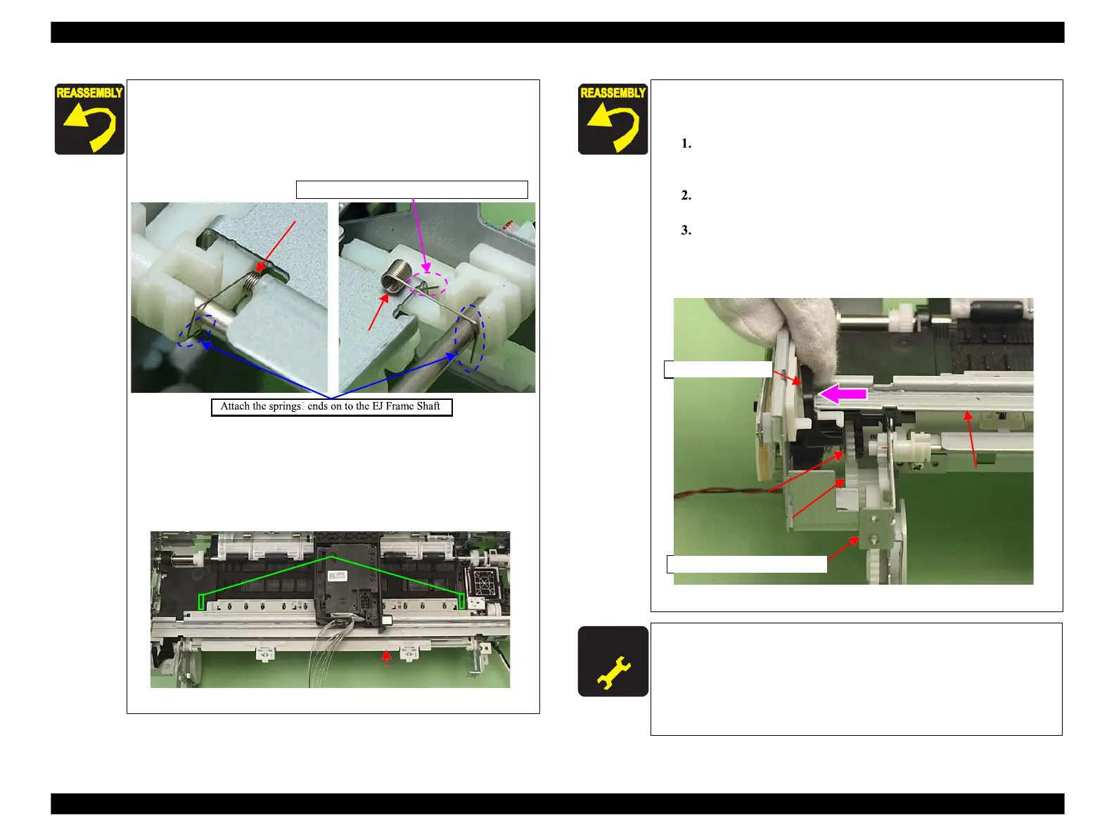
Make sure to attach the grounding springs (x2) of the EJ
Frame Assy securely to the EJ Frame Shaft. (See Fig. 4-112,
Fig. 4-114.)
Figure 4-114. Attaching the grounding spring
Align the dowel (x1) of the EJ Release Frame Assy R with the
positioning hole (x1) of the Main Frame. (SeeFig. 4-110.)
When attaching the Spur Gear A, insert the protrusion of the
EJ Frame Assy to the hole of the Paper Guide Front Assy.
Figure 4-115. Installing the EJ Frame Assy
After installing the EJ Release Frame Assy L, follow the
procedure below to check the movement of the EJ Release
Trigger.
Rotate the EJ Roller counterclockwise as seen from the left
side, and make the EJ Release Trigger stay on the CR
Guide Plate.
Lift the CR Guide Plate slightly and push the EJ Release
Trigger to the 80 digit side.
Make sure to engage the Spur Gear of the EJ Release
Trigger properly with the Combination Gear of the EJ
Release Frame Assy L, and check if the drive force of the
PF Motor transmits up to the EJ Frame Assy.
Figure 4-116. Check for EJ Release Trigger movement
EJ Release Frame Left Assy
After removing the EJ Frame Assy/EJ Release Frame Assy L/
R, make the specified adjustments. (See Chapter 5
"ADJUSTMENT".)
After replacing the EJ Frame Assy/EJ Release Frame Assy L/
R, be sure to perform the required lubrication. (See
 Loading...


