Epson Artisan 800/Epson Stylus Photo PX800FW/TX800FW/Epson Artisan 700/Epson Stylus Photo PX700W/TX700W
https://www.manualsbooks.com
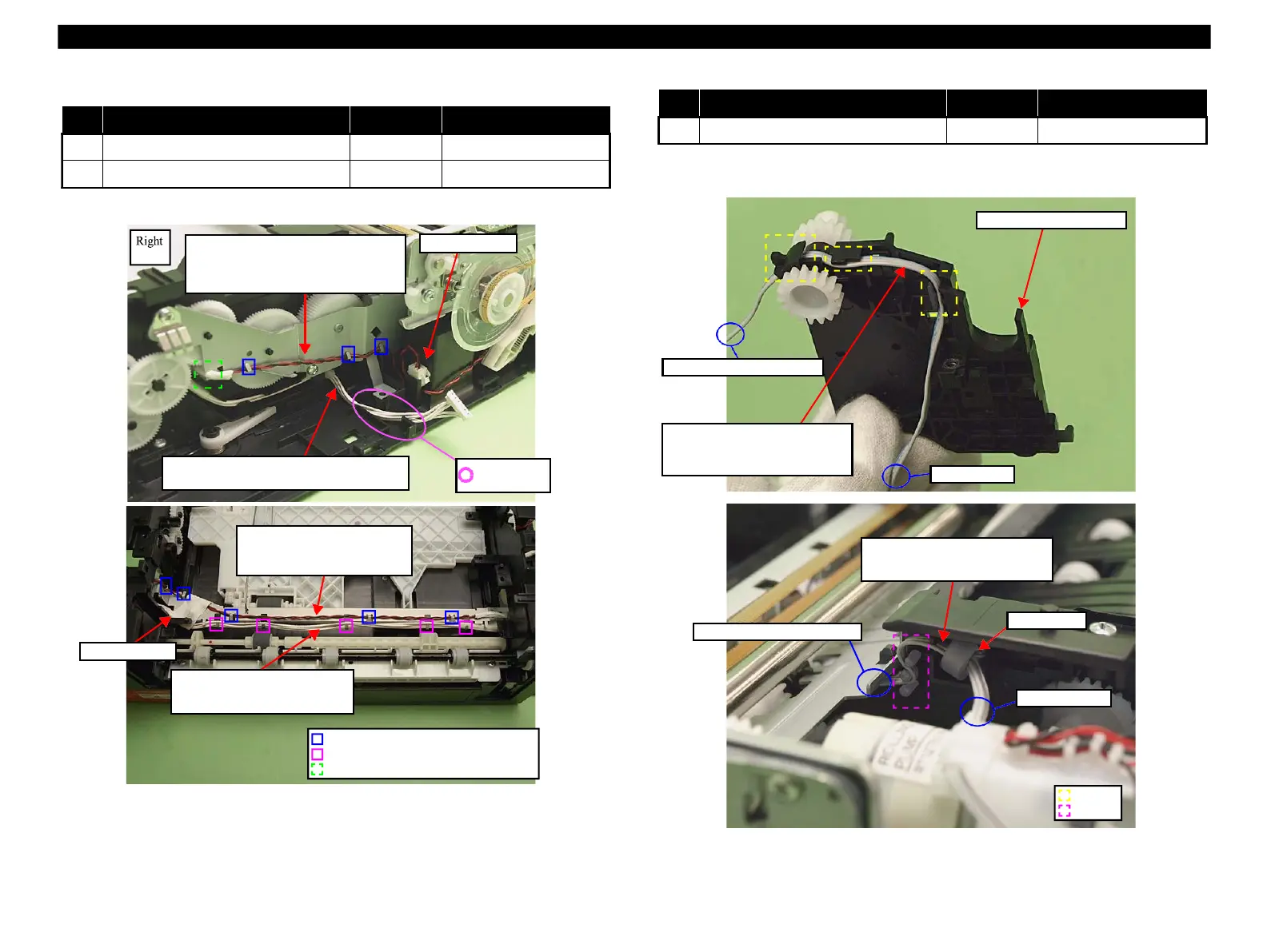
Note * : See Fig. 4-245 for the connector positions on the Main Board.
Figure 4-255. PF Motor Cable, Power Supply Unit Cable
Note "*": See Fig. 4-245 for the connector positions on the Main Board.
Figure 4-256. PE Sensor Cable
PF Motor cable:
Place the relay connector to the hole on
Base Frame, and route the cable through
the hooks (x3) and the groove (x1).
Hook securing PF Motor cable
Hook securing Power Supply Unit cable
Groove
Power Unit cable:
Route this through the hooks (x5)
and secure it with acetate tape.
PF Motor cable:
Route through the hooks (x5)
and secure with the acetate tape.
Do not let this
get caught.
Power Supply Unit cable:
Route this through the groove on Base Frame.
PE Sensor cable:
Route this through the grooves (x3)
of Transmission Holder Assy.
To the dowel of Base Frame
To Transmission Holder Assy
PE Sensor cable:
Route this through the dowels, and
attach ferrite core into Base Frame.
 Loading...


