• USB console port.
• RJ45 RS-232c serial console port used to connect a terminal and perform local management.
• LEDs to indicate port status and switch operating conditions. For a description of the LEDs and their
operation, see ExtremeSwitching X870 Series Switch LEDs on page 116.
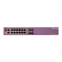
Figure 111: ExtremeSwitching X870-32c Front Panel
1 = Precision Timing ports (not supported) 4 = QSFP28/QSFP+ Ethernet ports
2 = Storage port: micro USB A 5 = Console port: RJ45
3 = Console port: micro USB B 6 = Ethernet management port: RJ45
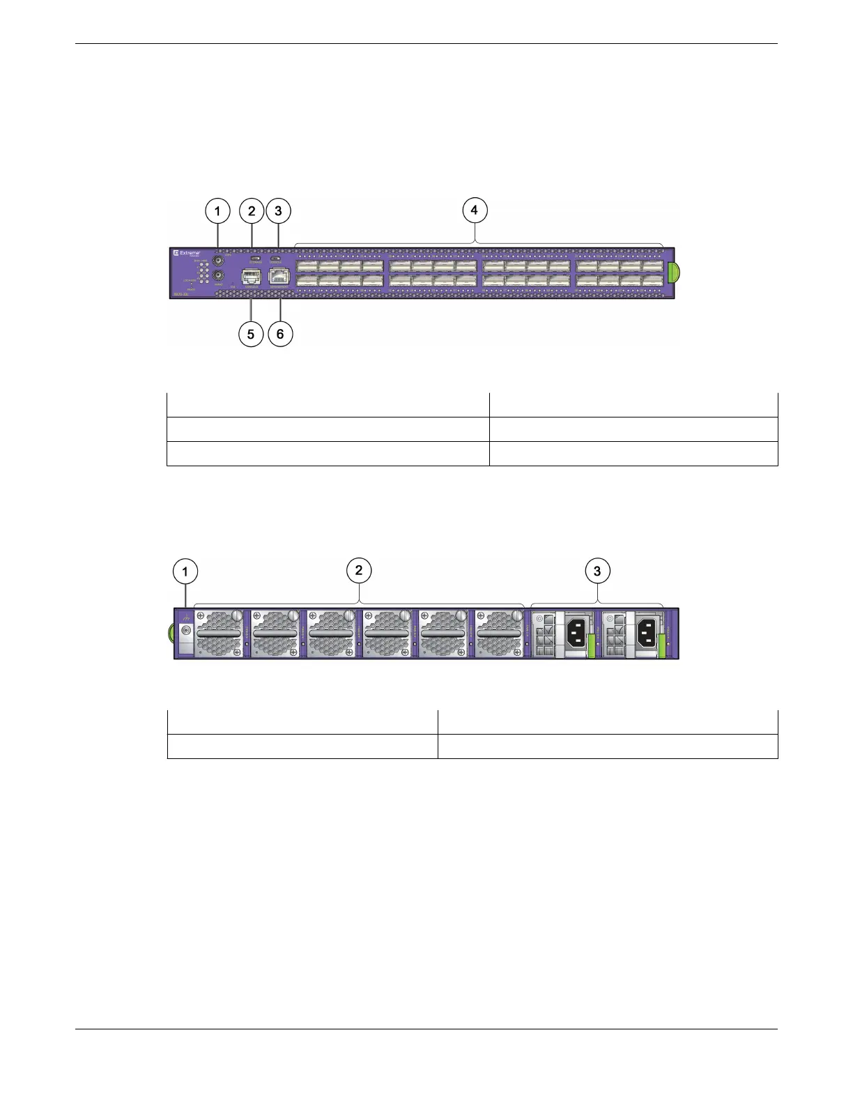
The rear panel of the ExtremeSwitching X870-32c switch includes:
• Six replaceable fan modules.
• Two power supply bays for either AC or DC power supplies.
Figure 112: ExtremeSwitching X870-32c Rear Panel
1 = Grounding lug
3 = AC power supplies
2 = Fan modules
ExtremeSwitching X870-96x-8c Switch Ports and Slots
The front panel of the ExtremeSwitching X870-96x-8c switch includes:
• Eight 100-gigabit Ethernet ports capable of supporting passive copper QSFP28/QSFP+ and active
fiber QSFP28/QSFP+ and configurable for 100 Gb, 40 Gb, 2x50 Gb, 4x25 Gb, and 4x10 Gb modes.
For information about QSFP28 and QSFP+ optical modules, see the Extreme Networks Pluggable
Transceivers Installation Guide.
• 24 100-gigabit Ethernet ports capable of supporting passive copper QSFP28/QSFP+ and active
fiber QSFP28/QSFP+ and restricted to 4x10 Gb Ethernet mode
ExtremeSwitching Switches
ExtremeSwitching X870-96x-8c Switch Ports and Slots
ExtremeSwitching Hardware Installation Guide 115
 Loading...
