CONSOLE
Summit
™
X450-G2-24t-10GE4
10GbES FP+
25
27
28
26
MGT FAN P1 P2 S
1 2 3 4 5 6 7 8 9
10 11 12 13 14 15 16
18
17 19
20
21
22
23
24
CLK ACT LINK
S2
STACK NO.
Management
5
3
4
1
2
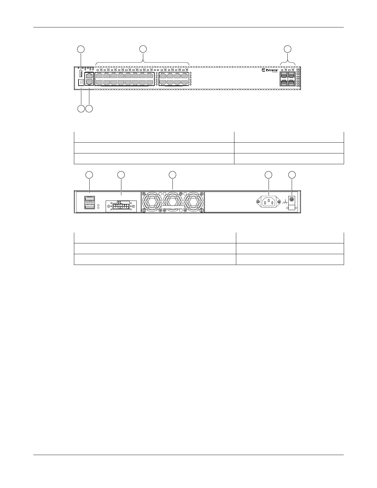
Figure 40: X450-G2-24t-10GE4 Front Panel
1 = Stack number indicator 4 = 10/100/1000BASE-T ports
2 = Console port/Ethernet management port 5 = SFP+ 10GBASE-X ports
3 = USB port
Redundant P ower Input
! See M anual
1
2
SummitStack-V84
4 531 2
Figure 41: X450-G2-24t-10GE4 Rear Panel
1 = 21 Gb stacking ports (QSFP+)
4 = AC power input connector
2 = Redundant power supply (RPS) connector 5 = Grounding screw
3 = Front-to-back fan module slot
ExtremeSwitching X450-G2-48t-GE4 Switch Ports and Slots
X450-G2-48t-GE4 switch ports and slots include:
• 48 front panel ports of 10/100/1000BASE-T (ports 1–48).
• Four front panel ports of 1GBASE-X SFP (ports 49–52).
• One front panel USB port.
• Ethernet management port 1 x 10/100/1000BASE-T.
• Serial console port implemented as an RJ45 connector used to connect a terminal and perform local
management.
• One
fixed power supply.
• One rear redundant power supply connector.
• One rear slot for fan module with front-to-back
airflow.
• Two dedicated QSFP-form factor 21 Gb stacking ports on the rear panel.
ExtremeSwitching X450-G2-48t-GE4 Switch Ports and
Slots ExtremeSwitching Switches
50 ExtremeSwitching Hardware Installation Guide
 Loading...
