• Ethernet management port (10/100/1000BASE-T).
• Serial console port implemented as an RJ45 connector used to connect a terminal and perform local
management.
• Front panel USB port.
• Rear dual PSU power slots with front-to-back or back-to-front airflow.
• Four rear slots for fan modules with front-to-back or back-to-front airflow.
Note
Two additional fan slots are unused. Do not remove the cover plate from the unused slots.
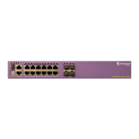
Figure 86: X590-24x-1q-2c Front Panel
1 = Console/management port
4 = 10Gb/40Gb QSFP+ port
2 = USB port 5 = 10Gb/25Gb/40Gb/50Gb/100Gb QSFP28 ports
3 = 1 Gb/10GBASE-X SFP+ ports
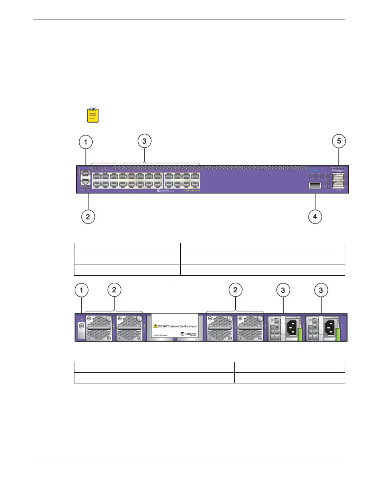
Figure 87: X590-24x-1q-2c Rear Panel
1 = Grounding lug
3 = AC power input
2 = Replaceable fan modules
ExtremeSwitching X590 Series Switch LEDs
The following tables describe the meanings of the LEDs on the front panel of the X590 series switch.
ExtremeSwitching Switches
ExtremeSwitching X590 Series Switch LEDs
ExtremeSwitching Hardware Installation Guide 87
 Loading...
