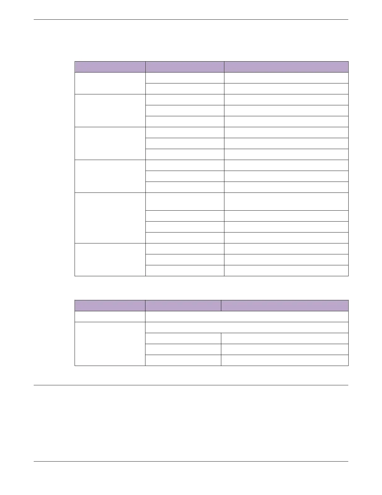
Table 27: X620 Front Panel LEDs (continued)
Label or Type Color/State Meaning
S1, S2 (Stack
Management)
Steady green Link OK on the indicated stacking port
Blinking green Activity on the indicated stacking port
FAN Steady green Normal operation
Blinking amber Failure
O No power
Power Supply Unit (PSU) Steady green Normal operation
Blinking amber Input or output power failure
O Not present
Redundant Power Supply
(RPS)
Steady green Normal operation
Blinking amber When RPS is present, no supply from PSU
O No RPS PSU is attached
Ethernet Management
Port
Blinking green (left) Activity on the indicated port
Link OK
O (left) Activity on the indicated port
Steady green (right) Link OK
O (right) No link, or port disabled
Other ports Steady green Link OK
Blinking green Activity on the indicated port
O No link, or port disabled
Table 28: ExtremeSwitching X620 2-digit Stack Number Indicator
Label or Type Color/State Meaning
Left digit (1) Reserved for future use.
Right digit (1 – 8) Indicates the position of this switch in the stack configuration
Upper half blinking This switch is the stack master node
Lower half blinking This switch is the stack backup node
Lit steadily This switch is a standby node in the stack
ExtremeSwitching X670-G2 Series Switches
The X670-G2 series switches have 48 or 72 front-panel Ethernet ports that can provide 10-gigabit
Ethernet connectivity using installable SFP+ optical modules. In addition, the X670-G2-48x-4q series
switches oer four QSFP+ ports.
The X670-G2 series switches include the following base models:
• ExtremeSwitching X670-G2-48x-4q Switch Ports and Slots on page 98
• ExtremeSwitching X670-G2-72x Switch Ports and Slots on page 99
ExtremeSwitching X670-G2 Series Switches
ExtremeSwitching Switches
96 ExtremeSwitching Hardware Installation Guide
 Loading...
