MGT FAN P1 P2 S1
CLK ACT LINK
S2
21
22
23
24
17
18
19
20 25
26
27
28 29 30
31
32
36
37
38
39 40
41
42
43
46
44 47
45
48
33
34
35
50
51
49
52
1 2 3 4 5 6 7 8 9
10 11 12 13 14 15 16
CONSOLE
STACK NO.
Management
5
3
4
1
2
Summit
™
X450-G2-48p-10GE4
10GbES FP+
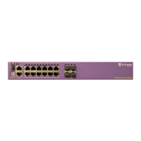
Figure 52: X450-G2-48p-10GE4 Front Panel
1 = Stack number indicator 4 = PoE+ 10/100/1000BASE-T ports
2 = Console port/Ethernet management port 5 = SFP+ 10GBASE-X ports
3 = USB port
PSU -2PS
IN.OK
AIR OUT
(AFO)
OUT. OK
115V-240V- 12-6A 50-60Hz
CLEI LABEL
U-1
SummitStack-V84
431 2
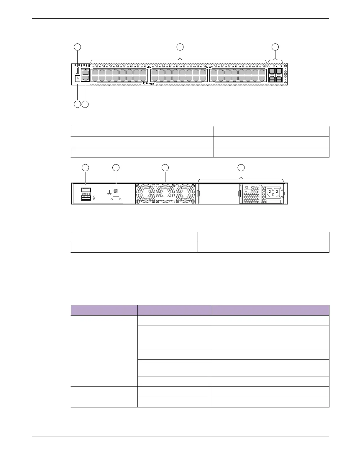
Figure 53: X450-G2-48p-10GE4 Rear Panel
1 = 21 Gb stacking ports (QSFP+)
3 = Front-to-back fan module slot
2 = Grounding screw 4 = PoE+ power supply bays
ExtremeSwitching X450-G2 Series Switch LEDs
The following sections describe the meanings of the LEDs on X450-G2 series switches.
Table 12: X450-G2 Front Panel LEDs
Label or Type Color/State Meaning
M (Management) Slow blinking green (1 Hz) Normal operation
Fast blinking green (2 Hz) Power-on self test (POST) in progress
or
Switch diagnostics are running
Steady green POST passed: system is booting image
Blinking amber System is disabled: POST failed or system
overheated
O No external power is attached
S1, S2 (Stack
Management)
Steady green Link OK on the indicated stacking port
Blinking green Activity on the indicated stacking port
ExtremeSwitching X450-G2 Series Switch LEDs ExtremeSwitching Switches
56 ExtremeSwitching Hardware Installation Guide
 Loading...
