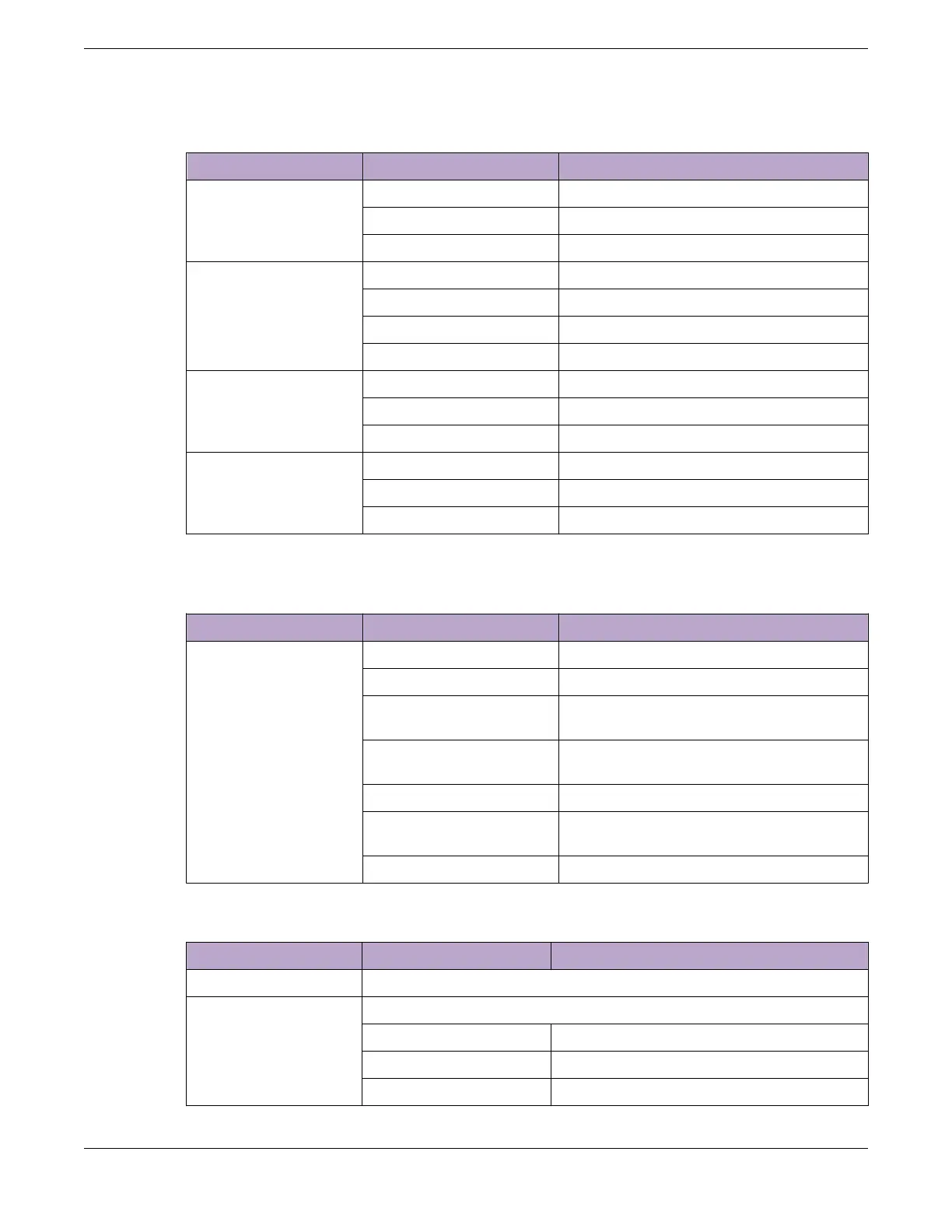
Table 12: X450-G2 Front Panel LEDs (continued)
Label or Type Color/State Meaning
FAN Steady green Normal operation
Blinking amber Failure
O No power
P1, P2 (Power Supply) Steady green Normal operation
Steady amber Power is attached, but no power is on
Blinking amber Power failure
O No power attached
Ethernet Port 1–24 or 1–
48
Steady green Link OK
Blinking green Activity on the indicated port
O No link or port disabled
1G SFP ports or 10G SFP+
ports 25, 26, 27, and 28
or 49, 50, 51, and 52
Steady green Link OK
Blinking green Activity on the indicated port
O No 1G or 10G link, or port disabled
Table 13: Additional Port LED Meanings for PoE Switches: X450-G2-24p-GE4, X450-
G2-24p-10GE4, X450-G2-48p-GE4, and X450-G2-48p-10GE4
Label or Type Color/State Meaning
All front panel ports 1-24
or 1-48
Steady green Link is OK; port is not powered
Steady amber Link is OK; port is powered; no trac
Blinking green Link is OK and transmitting packets; port is
not powered
Blinking amber Link is OK and transmitting packets; port is
powered
Slow blinking amber No link, or disabled port; port is powered
Alternating amber and
green
Port has a power fault
O Port is not powered, has no link, or is disabled
Table 14: X450-G2 2-digit Stack Number Indicator
Label or Type Color/State Meaning
Left digit (1) Reserved for future use.
Right digit (1–8) Indicates the position of this switch in the SummitStack configuration
Upper half blinking This switch is the stack master node
Lower half blinking This switch is the stack backup node
Lit steadily This switch is a standby node in the stack
ExtremeSwitching Switches ExtremeSwitching X450-G2 Series Switch LEDs
ExtremeSwitching Hardware Installation Guide 57
 Loading...
