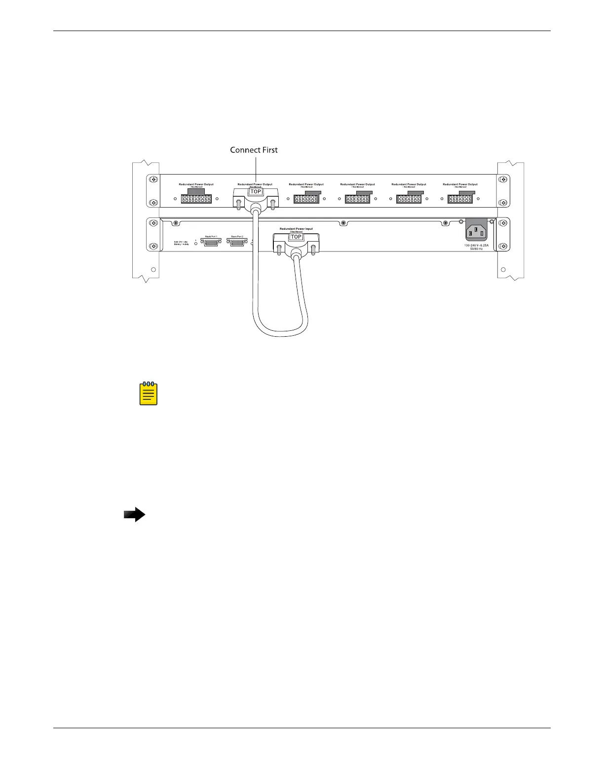
4. Connect the other end of the redundant power cable (for the 2x7 connector cable, the end with the
key flush with the edge of the connector pins) to the switch.
See Figure 212.
Be sure that the side of the connector marked TOP is facing up.
Figure 212: Installing the Redundant Power Cord
Note
The EPS-C2 2x9 connector, shown in the figure to the left of where the cable is connected,
is used only with older switch models that are not compatible with ExtremeXOS version
21.1 and later.
5. Repeat the preceding steps to connect any additional redundant power cords.
Connecting the AC Power cord to the EPS-C2
Important
When performing this task, observe all of the precautions listen in Safety Considerations for
Installing Power Supplies on page 263.
Connecting the AC Power cord to the EPS-C2 Installing External Power Supplies
270 ExtremeSwitching Hardware Installation Guide
 Loading...
