• One front panel USB 2.0 port, operational on switches running ExtremeXOS version 22.2 or later.
• One rear redundant power supply connector.
The X440-G2 24t-GE4 switch supports an operating range from 0°C to 60°C.
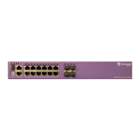
Figure 36: ExtremeSwitching X440-G2-24t-GE4 Front Panel
1 = Stack number indicator 3 = USB port (active with ExtremeXOS version 22.2 or later)
2 = Console port/Ethernet management port 4 = 10/100/1000BASE-T ports
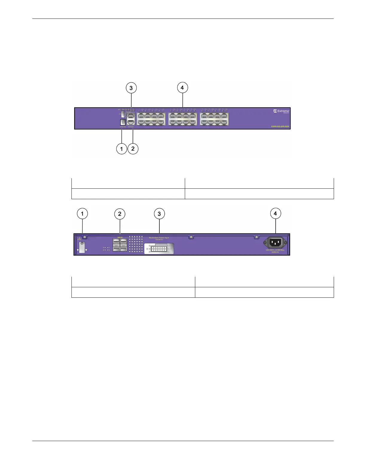
Figure 37: ExtremeSwitching X440-G2-24t-GE4 Rear Panel
1 = Grounding lug
3 = Redundant power input
2 = 1GBASE-X SFP ports 4 = AC power input socket
ExtremeSwitching X440-G2 Series Switch LEDs
The following sections describe the meanings of the LEDs on the ExtremeSwitching X440-G2 series
switches.
ExtremeSwitching Switches
ExtremeSwitching X440-G2 Series Switch LEDs
ExtremeSwitching Hardware Installation Guide 45
 Loading...
