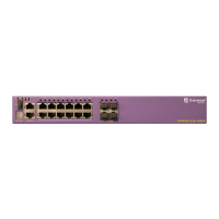
Figure 96: ExtremeSwitching X620-16p Front Panel
1 = Stack number indicator 4 = 100Mb/1 Gb/2.5G/5G/10GBASE-T ports
2 = Console port/Ethernet management port 5 = 100Mb/1 Gb/10GBASE-T ports
3 = USB port 6 = 1 Gb/10GBASE-X SFP+ combo ports
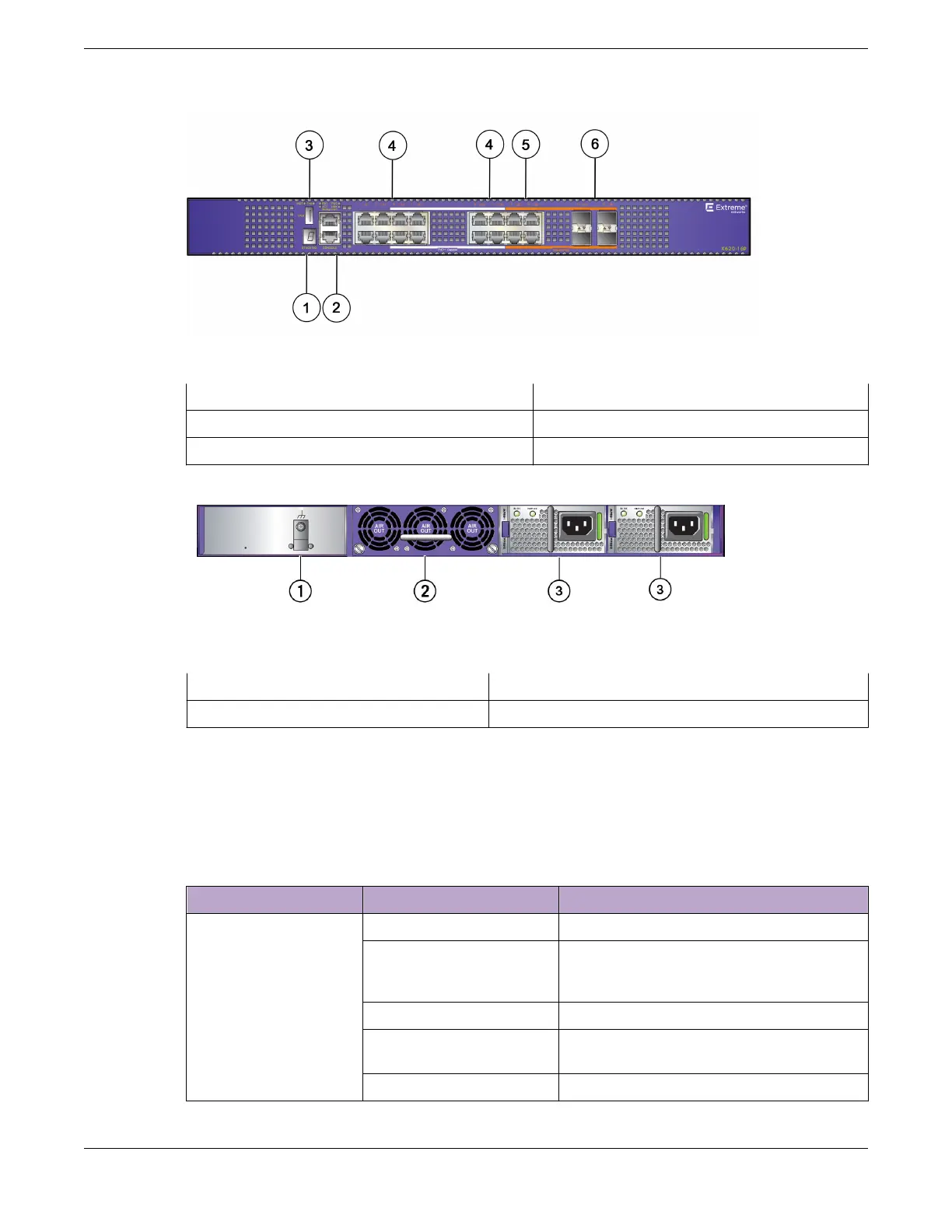
Figure 97: ExtremeSwitching X620-16p Rear Panel
1 = Grounding lug
3 = AC power supplies
2 = Fan module
ExtremeSwitching X620 Series Switch LEDs
The following sections describe the meanings of the LEDs on the ExtremeSwitching X620 series
switches.
Table 27: X620 Front Panel LEDs
Label or Type Color/State Meaning
M (Management) Slow blinking green (1 Hz) Normal operation
Fast blinking green (2 Hz) Power-on self test (POST) in progress
or
Switch diagnostics are running
Steady green POST passed: system is booting image
Blinking amber System is disabled: POST failed or system
overheated
O No external power is attached
ExtremeSwitching Switches ExtremeSwitching X620 Series Switch LEDs
ExtremeSwitching Hardware Installation Guide 95
 Loading...
