b. Insert and tighten the retaining screws you removed in step 3. The clock module uses Phillips
screws and the VIM and SSD modules use slotted screws.
1
Soli d ON=Li nk
Blin king= Activ ity
S1 S 2
Su mmit X46 0-G2 VIM-2x
TM
1 0GbE S FP +
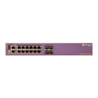
Figure 310: Tighten Screws on the Inserted VIM5 Module
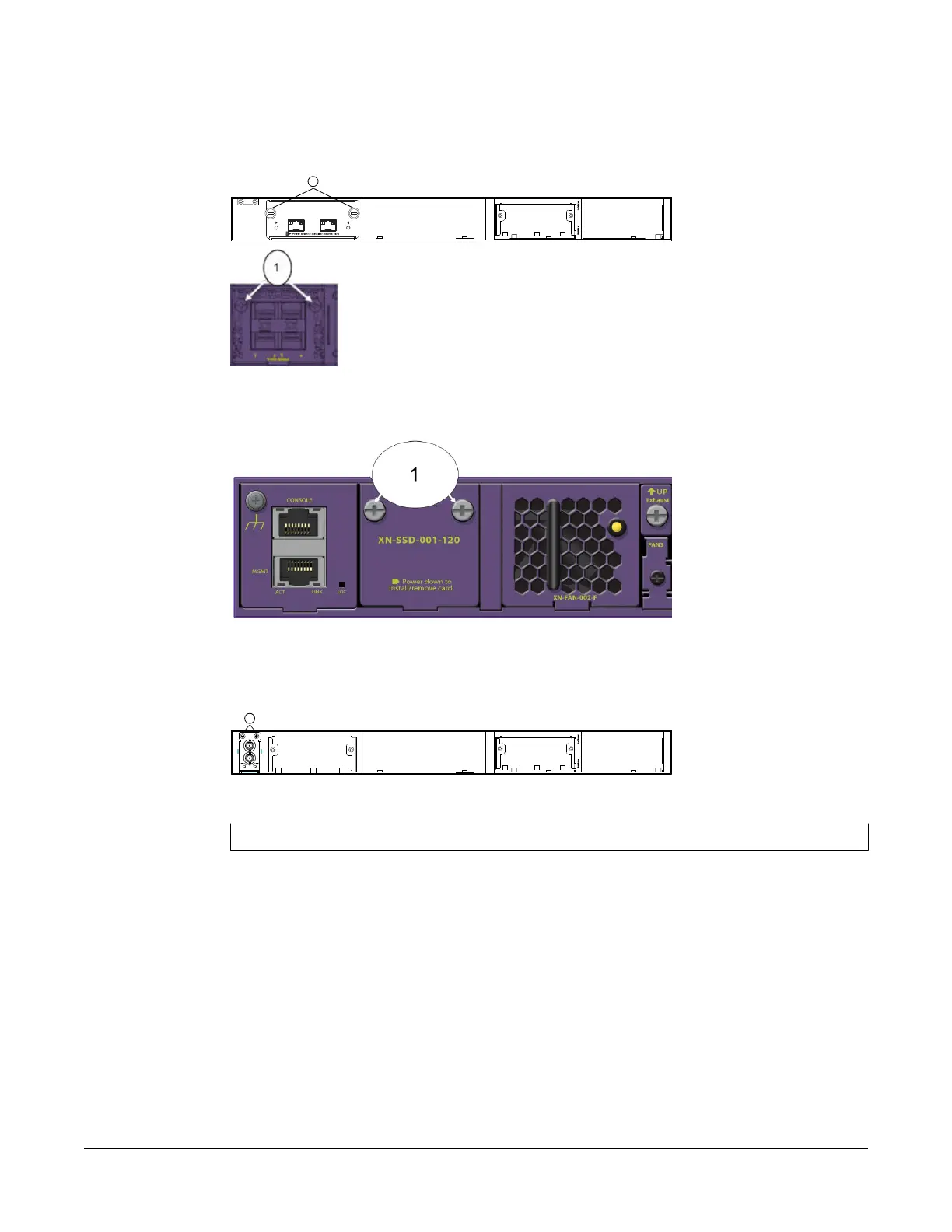
Figure 311: Tighten Screws on the Inserted SSD Module
1
11 PP
PP
SS
11
00 MM
HH
zz
OO
UU
TT
PP
UU
TT
TT MM--CC LL KK
Figure 312: Tighten Screws on the Inserted Clock Module
1= retaining screw locations
Removing and Replacing Expansion Modules
Replacing a Versatile Interface Module, Solid-state Drive,
or Clock Module in an X460-G2 Series or X465 Series
Switch
ExtremeSwitching Hardware Installation Guide 373
 Loading...
