Ethernet Automatic Protection Switching
ExtremeWare XOS 11.3 Concepts Guide
420
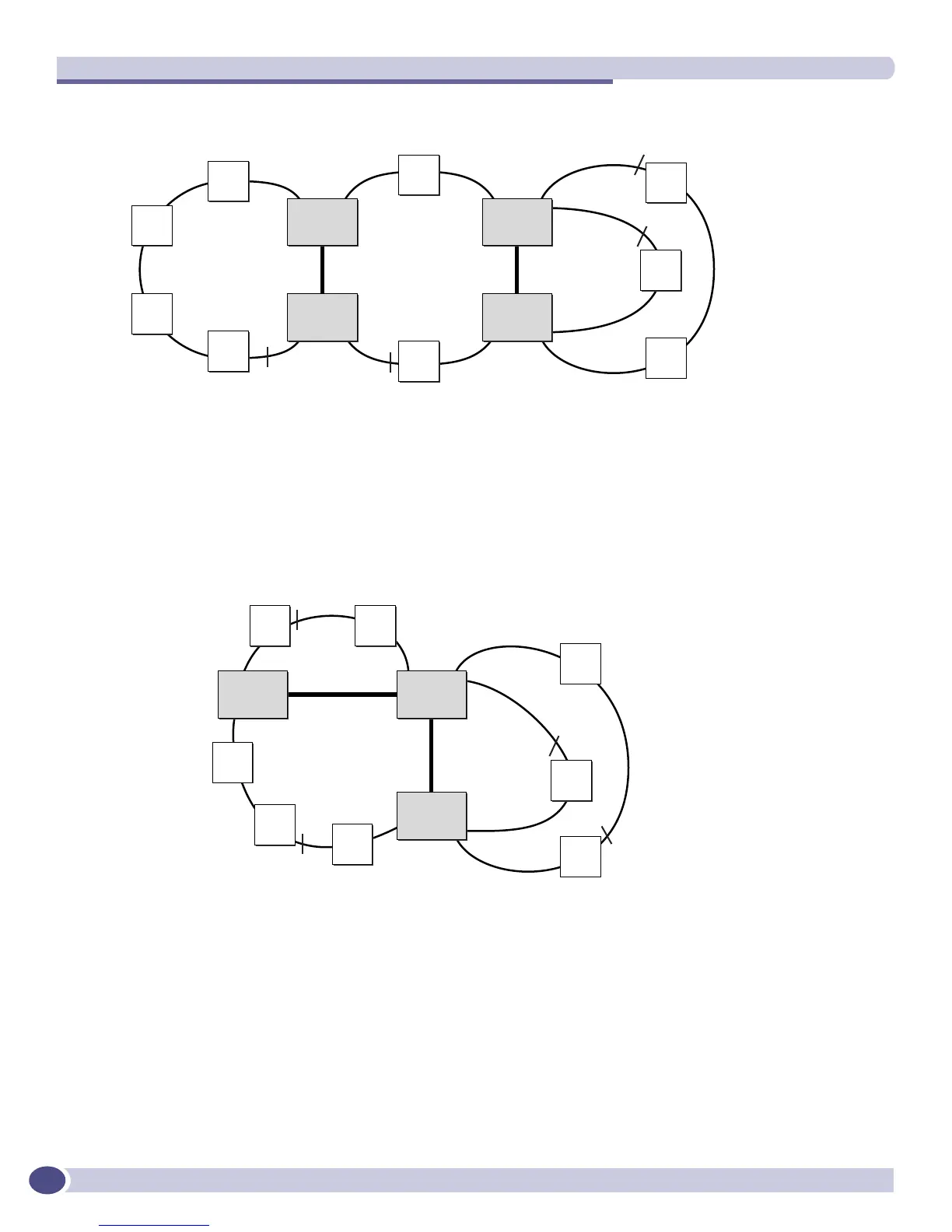
Figure 27: EAPS shared port basic core configuration
Right Angle Configuration
In this topology, there are still two EAPS common links, but the common links are adjacent to each
other. To configure a right angle configuration, there must be two common links configured on one of
the switches. Figure 28 shows a Right Angle configuration.
Figure 28: EAPS shared port right angle configuration
Combined Basic Core and Right Angle Configuration
Figure 29 shows a combination Basic Core and Right Angle configuration.
EW_096
S 4
S 3
S 2
S 1
Partner
EAPS1
S 8
S 7
S
5
S
6
EAPS2
Controller
Partner
S 12
S 13
S 11
S
9
S
10
Common link
Common link
EAPS3
EAPS4
Controller
link ID=1
link ID=2
P1:1
P1:2 P1:3
Master
node
Master
node
Master
node
Master
node
P
S
S
P
S
S
P
P
EW_097
S 5
S 3
S 2
S 1
EAPS1
S 6
S
4
EAPS2
Controller
Partner
S 10
S 11
S 9
S
7
S
8
Common
link
Common
link
EAPS3
EAPS4
Partner
Controller
link ID=2
link ID=1
Master
node
S
P
Master
node
S
P
Master
node
S
P
Master
node
S
P
 Loading...