Configuring Slots and Ports on a Switch
ExtremeWare XOS 11.3 Concepts Guide
140
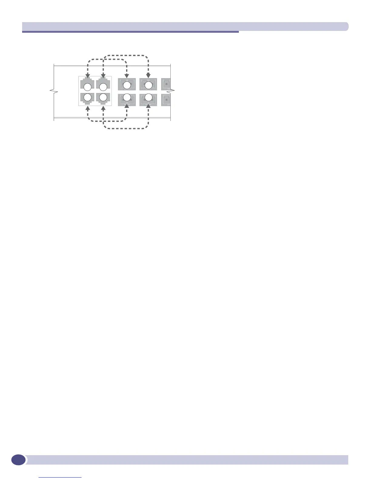
Figure 3: Redundancy cabling for the SummitX450-24x switch
The switch determines whether the port uses the primary or redundant media based upon the order in
which the connectors are inserted into the switch. When the switch senses a mini-GBIC and a copper
connector are inserted, the switch enables the uplink redundancy feature. As an example on the Summit
X450-24t switch, if you insert mini-GBICs into fiber port 1 and fiber port 3 first and then connect copper
ports 1 and 3, the switch assigns ports 1 and 3 as redundant ports.
Hardware determines when a link is lost and swaps the primary and redundant ports to maintain
stability. After a failover occurs, the switch keeps or sticks with the current port assignment until there
is another failure or until a user changes the assignment using the CLI. To change the uplink failover
assignment, use the following command:
configure ports <port_list> preferred-medium [copper | fiber] {force}
The default preferred-medium is fiber. If you use the force option, it disables automatic failover. If you
force the preferred-medium to fiber and the fiber link goes away, the copper link is not used, even if
available.
Displaying Port Configuration Information
You display summary port configuration information using the show ports {mgmt | <port_list>}
configuration {no-refresh},
show ports {mgmt | <port_list>} information {detail},
commands.
The
show ports configuration command shows you either summary configuration information on
all the ports, or more detailed configuration information on specific ports. If you specify the
no-
refresh
parameter, the system displays a snapshot of the data at the time you issue the command.
The following sample output is from the
show ports configuration command on a modular switch
and displays the port configuration for all ports:
show ports configuration
Port Configuration
Port Virtual Port Link Auto Speed Duplex Flow Load Media
router State State Neg Cfg Actual Cfg Actual Cntrl Master Primary
================================================================================
1:1 VR-Default E A ON AUTO 100 AUTO FULL SY/ASYM UTP
1:2 VR-Default E R ON AUTO AUTO UTP
2:1 VR-Default E R ON AUTO AUTO UTP
2:2 VR-Default E R ON AUTO AUTO UTP
1
2
3
4
1
2
3
4
S450_005
 Loading...