OSPF Configuration Example
ExtremeWare XOS 11.3 Concepts Guide
553
OSPF Configuration Example
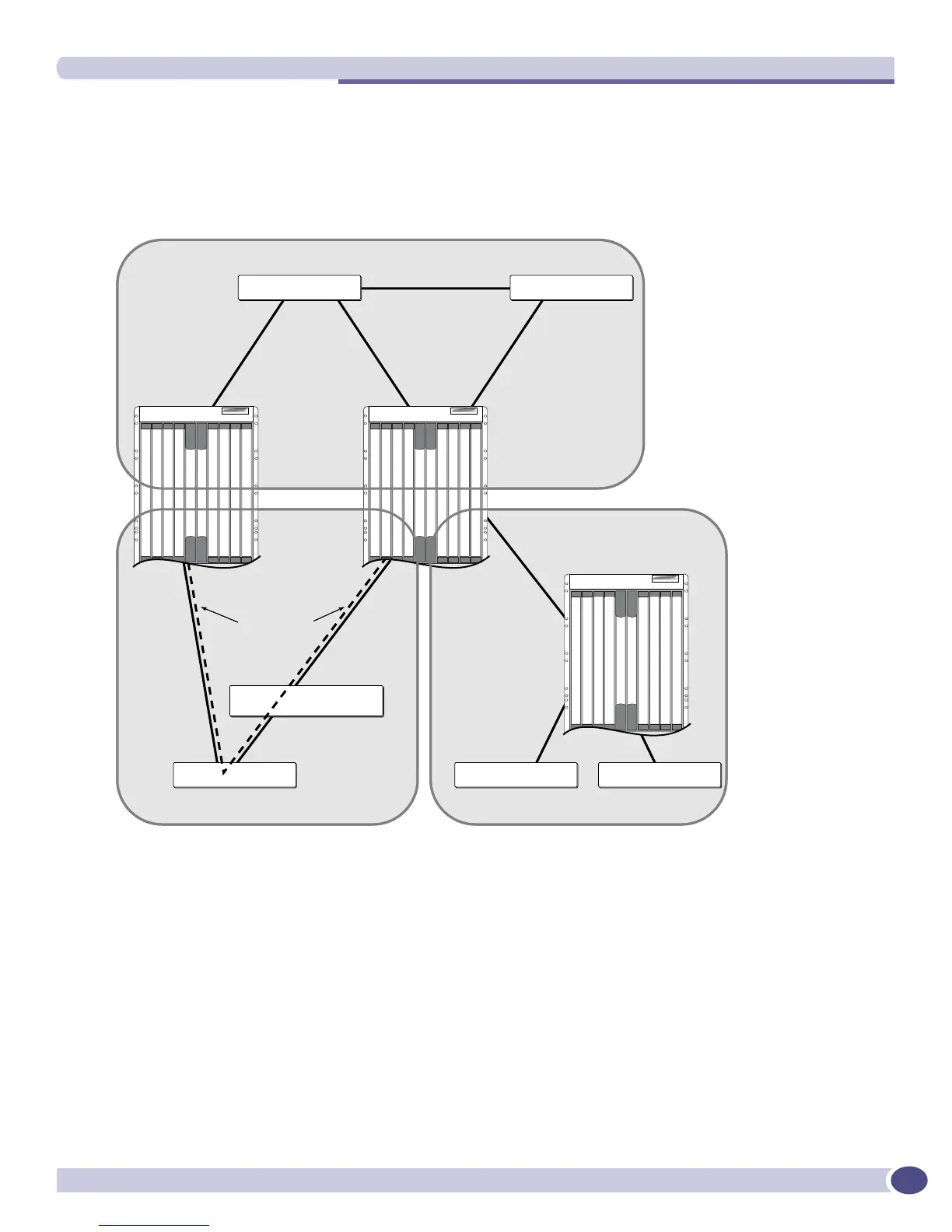
Figure 71 is an example of an autonomous system using OSPF routers. The details of this network
follow.
Figure 71: OSPF configuration example
Area 0 is the backbone area. It is located at the headquarters and has the following characteristics:
● Two internal routers (IR1 and IR2)
● Two area border routers (ABR1 and ABR2)
● Network number 10.0.x.x
● Two identified VLANs (HQ_10_0_2 and HQ_10_0_3)
Area 5 is connected to the backbone area by way of ABR1 and ABR2. It is located in Chicago and has
the following characteristics:
● Network number 160.26.x.x
● One identified VLAN (Chi_160_26_26)
● Two internal routers
Area 0
10.0.1.1
10.0.3.2
10.0.3.1
160.26.25.1
161.48.2.2
161.48.2.1
10.0.2.1
HQ_10_0_2
Chi_160_26_26
HQ_10_0_3
10.0.2.2
10.0.1.2
Area 6 (stub)
Virtual link
IR 2 IR 1
ABR 1ABR 2
Headquarters
Los Angeles
EX_040
LA_161_48_2
160.26.26.2
Area 5
Chicago
160.26.25.2
160.26.26.1
 Loading...