STP Configurations
ExtremeWare XOS 11.3 Concepts Guide
431
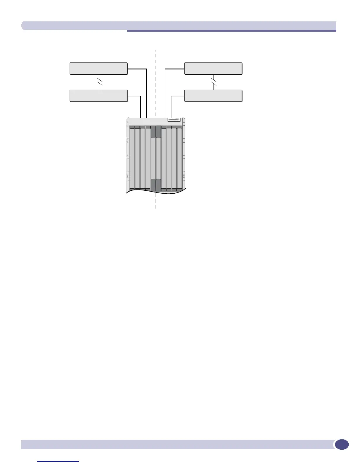
Figure 32: Multiple STPDs
When the switches in this configuration boot-up, STP configures each STPD such that the topology
contains no active loops. STP could configure the topology in a number of ways to make it loop-free.
In Figure 32, the connection between switch A and switch B is put into blocking state, and the
connection between switch Y and switch Z is put into blocking state. After STP converges, all the
VLANs can communicate, and all bridging loops are prevented.
The protected VLAN Marketing, which has been assigned to both STPD1 and STPD2, communicates
using all five switches. The topology has no loops, because STP has already blocked the port connection
between switch A and switch B and between switch Y and switch Z.
Within a single STPD, you must be extra careful when configuring your VLANs. Figure 33 illustrates a
network that has been incorrectly set up using a single STPD so that the STP configuration disables the
ability of the switches to forward VLAN traffic.
Sales, Personnel, Marketing
STPD 1
STPD 2
Manufacturing, Engineering, Marketing
Sales, Personnel, Manufacturing, Engineering, Marketing
Switch A Switch Y
Switch Z
Switch M
Switch B
EX_048
 Loading...