C O N F I D E N T I A L – FEI Limited Rights Data 2-1
2
System Control
This chapter describes the layout of the system, interface elements and equipment.
System Layout
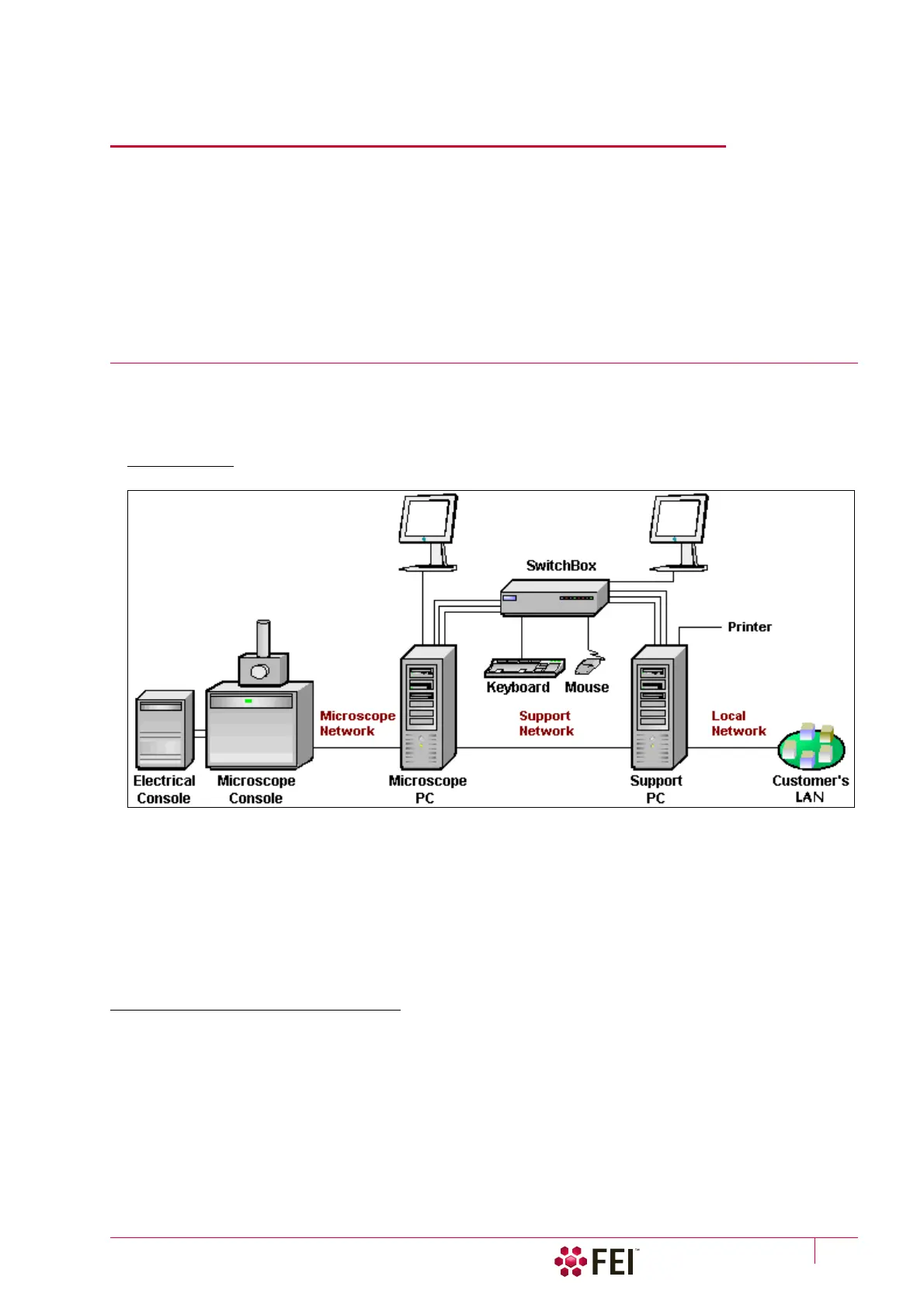
The basic system layout is based around the dedicated Microscope PC with the LCD monitor, Microscope console
and Electrical console. Optionally it is possible to have a second LCD monitor with the Microscope PC or the
Support PC with LCD monitor and the switch box with keyboard and mouse to switch between the two PC’s.
FIGURE 2-1 Scios Standard Layout Scheme
Caution!
If the equipment is used in a manner not specified by the manufacturer, the protection provided by the equipment may be
impaired.
Mains power must be connected to a grounded socket that is visible and easily accessible!
A user must not disconnect any parts of the equipment or connect any equipment not approved in this manual or in the
FEI Microscope Systems Safety Manual!
All power and external equipment connectors should be covered by stoppers (part of delivery) when not used!
Other Software and Hardware
Call a FEI authorized service engineer for advice before installing software or hardware that is not required for
system operation. Other software, such as screen savers or hardware network cards, may corrupt the
xT
microscope Server / Microscope Control software under some circumstances and may invalidate warranty.
For more detailed information about Windows 7™, refer to the Microsoft® Windows™ User’s Guide shipped with
your system.