Operating Procedures: Patterning
C O N F I D E N T I A L – FEI Limited Rights Data5-58
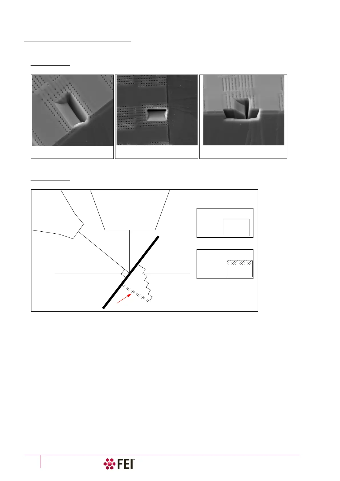
Viewing Cross Sections
After cutting the cross section, lower the ion beam current to 10 or 30 pA and tilt the stage to 52° to view the cross
section with the ion beam. The following figure shows examples of some typical milling of a cross section.
FIGURE 5-15 Cross-Section Views
The following figure shows the relation of the columns and stage to the face of the cross section during milling and
how this is viewed onscreen, depending on whether you are imaging with the electron or ion beam.
FIGURE 5-16 Cross-Section Viewing during Milling
Top view of the cross section Cross-section view. This view shows
the geometry of the cross section.
Perspective view of the cross section
milled on the edge of a sample
Ion column
Electron column
S
t
age
52° stage tilt
Cross-section face
Onscreen views
Ion beam
Cross-section face
(Not to Scale)
Not
visible
Completely
visible
Electron beam
Cross-section face