System Options: Beam Deceleration
C O N F I D E N T I A L – FEI Limited Rights Data7-30
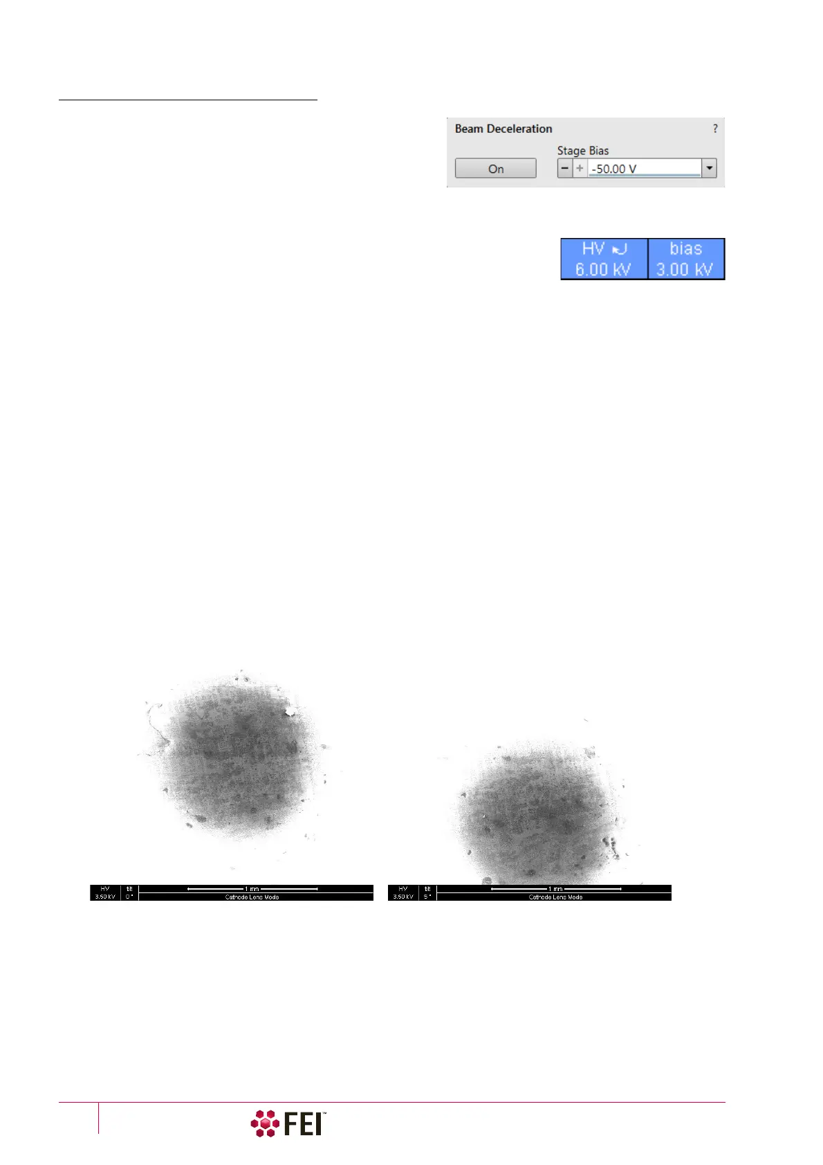
Beam Deceleration Module
The Beam Deceleration module has the following features:
• On button – switches the BD mode On / Off. This is
available only in the HiVac mode and with the Beam On.
When switching the beam off, the BD mode switches off
automatically.
• Stage Bias adjuster – reflects the voltage applied to a stage
from +50
V to -50 V, optionally to -4 000 V.
When the BD mode is on, a hook mark is placed behind the HV. In this case the
value represents energy of electrons reaching a sample surface (it is also stored
within the TIF file header).
imRatio = (Accelerating voltage + Stage Bias) / Accelerating voltage
Beam Deceleration Mode Imaging Procedure
1. Put the sample into the chamber and pump down to the HiVac.
In the BD mode a sample becomes the electrode. Its position, size, tilt and surface roughness influence an
imaging quality. At optimal conditions the sample should be symmetrical, planar, have a size comparable with
the detector size, and placed perpendicular to the column axis. In other conditions a distortion, astigmatism and
a blurring caused by the chromatic aberration appear. This is even worse when the Immersion Ratio is higher.
2. Select the suitable HV and find an area of interest. Set the Eucentric Position and tune an image with the Direct
Adjustments module / Beam and the Stigmator Centering tabs (see Chapter 5). In various displays get the SE and
BSE images to observe different imaging simultaneously.
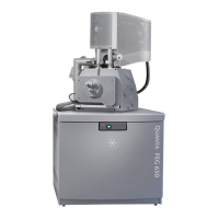
3. Click on the On button. Gradually raise the Stage Bias (lower voltage), the SE / BSE image is getting dark / light.
At low magnifications an ETD image should become dark symmetrically around the window center, in other
case the sample can be tilted.
When a dark area is shifted with a Stage Bias change, the sample is possibly not parallel with the detector. With
the use of the Compucentric stage rotation / stage tilt try to keep the dark area in the center of the screen.
Note
When a retractable detector is inserted, stage tilt is restricted via the UI. Overcome it manually (confirmation is
necessary) to keep the dark area in the center of the screen.
Note
An image shift when changing the Stage Bias can be caused by imaging near the sample edge or any other edge.
4. Set the Stage Bias considering the sample material (charging compensation, material contrast) and to optimize
the signal. Set the brightness, contrast and WD according to the requirement.
5. Tune the Direct Adjustments module / Beam and the Stigmator Centering tabs (both factors remember the HV and
Stage Bias last used).
6. Repeat steps 4 and 5 to get the best result.
Note
For the column Use case application suitable for the Beam Deceleration mode see the Help menu / User Guidance item.