Operating Procedures: Standard Detectors
C O N F I D E N T I A L – FEI Limited Rights Data 5-19
Standard Detectors
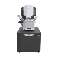
The Detectors menu and Detector Settings module / Detector list box show all installed
detectors, the selected one has a tick mark next to its label. When a Detector Settings
module / Mode is selected, its acronym is shown beside the detector label in the
Detectors menu. Availability of detectors (full color label) depends on the actual
conditions.
Detector selection is related to the display and to the active beam – the system always
reverts to the last detector used for that beam in that display and remembers
its Contrast & Brightness settings.
In addition to the standard detectors available, there may be optional ones available for
your system (see Chapters 2 and 7).
Note
If any detector which is not compatible with the actual vacuum mode is selected, the imaging
display cannot be activated.
Images from individual segments / detectors can be acquired simultaneously in up to four
different displays.
Caution!
When patterning or milling a large volume of material at higher ion currents, it is
recommended to remove any detector if it is not used. There is a risk of its efficiency
decrease by a material deposition.
WARNING!
To prevent stubbing with an EasyLift needle (option) follow the procedure described in the EasyLift section (see Chapter 7)!
Everhart Thornley Detector (ETD)
It is a scintillator photo-multiplier type detector collecting
electrons generated by the primary beam interaction with the
specimen surface. It is permanently mounted in the chamber
over and to one side of the sample. It works in Modes:
• Secondary Electrons (SE)
• Backscattered Electrons (BSE)
• Custom
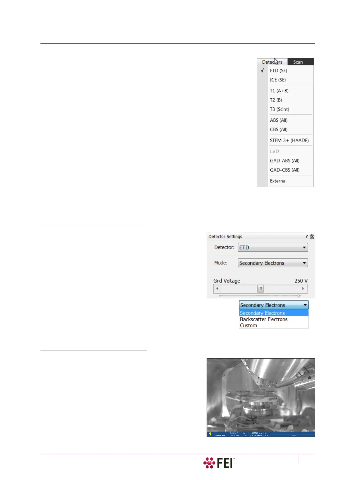
ETD Settings
The Detector Settings / Mode list box enables to choose an SE /
BSE mode (the Grid Voltage is set to +250 V / -150 V) or a Custom
mode, for which the Grid Voltage can be set by the adjuster in a
range from -240 to +260 V. When the voltage is negative (use a
range of -25 to -240 V), SE are repelled from the ETD detector
and only BSE are detected.
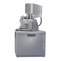
Infrared CCD Camera
Imaging obtained with this camera assists in overall sample and
stage orientation by viewing the inner space of the specimen
chamber (an optical imaging display). It helps to protect the
objective lens and retractable detectors against collision when
moving (especially in the Z-direction) or tilting the stage. IR LED’s
are used to light the specimen chamber interior.