Operating Procedures: Optimizing Imaging
C O N F I D E N T I A L – FEI Limited Rights Data5-16
Accelerating Voltage and Beam Currents
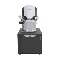
The choice of accelerating voltages – in the UI named High Voltage (HV) – and
Beam Currents for the active display is possible via the toolbar dropdown list
boxes and depends on the active beam type:
• For the electron beam, HV and current are independent, so any change of the voltage will not influence the
current.
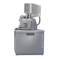
• For the ion beam, currents available are dependent on the HV selected; for example at 30 kV the current is 100
pA, however, the current reduces to 13
pA when the HV is set to 5 kV, even when used ion beam aperture
remains the same.
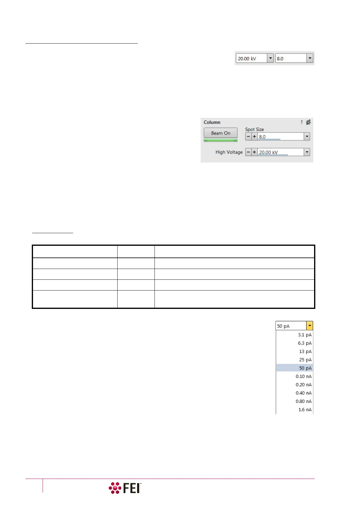
Changing High Voltage
Besides a normal list box behaviour an intermediate value can be
entered into the toolbar editable HV text box or set by the Column
module / High Voltage adjuster on the Beam control page. This
provides a calculated range of beam current / spot values.
Default values in the list box are set in the Preferences dialog /
Presets section.
Electron Beam Current
This is one of the basic operating parameters. In other way it is represented as the function of the electron beam
diameter (usually presented as the Spot size, expressed by a relative number from 1 to 20 in the Standard Use case
(depending also on the accelerating voltage) and from 2 to 18 in the OptiPlan and OptiTilt column Use cases), the
final lens aperture diameter and its opening angle set by the condenser. It is considered to be close to ideal when
spot edges just touch the neighbouring one. If it is too large, overlaps occur and the image appears out of focus. If it
is too small, electronic noise appears in the image.
A suitable beam current value for a particular magnification can be determined easily, when good focus and
astigmatism correction is achieved.
Changing Electron Beam Current
Either electron Beam Current or Spot Size can be shown within the User Interface. This can be set
in the Preferences dialog / General section or by right-clicking on the toolbar text box and
selecting the desired context menu proposal.
An intermediate value can be set by the Column module / Beam current/Spot size adjuster on the
Beam Control page. Default values in the list box are set in the Preferences dialog / Presets
section.
Table 5-2
Spot sizes and recommendation of their use
SEM Column Use Case Spot size Best Use
Standard / OptiTilt / OptiPlan 1–4 Very low currents, charging and sensitive samples
Standard / OptiTilt / OptiPlan
4–6 High resolution
Standard / OptiTilt / OptiPlan
6–12 Standard imaging
Standard / OptiTilt / OptiPlan
12
and more
High current imaging, X-ray analysis with SDD detectors