Operating Procedures: Standard Detectors
C O N F I D E N T I A L – FEI Limited Rights Data 5-21
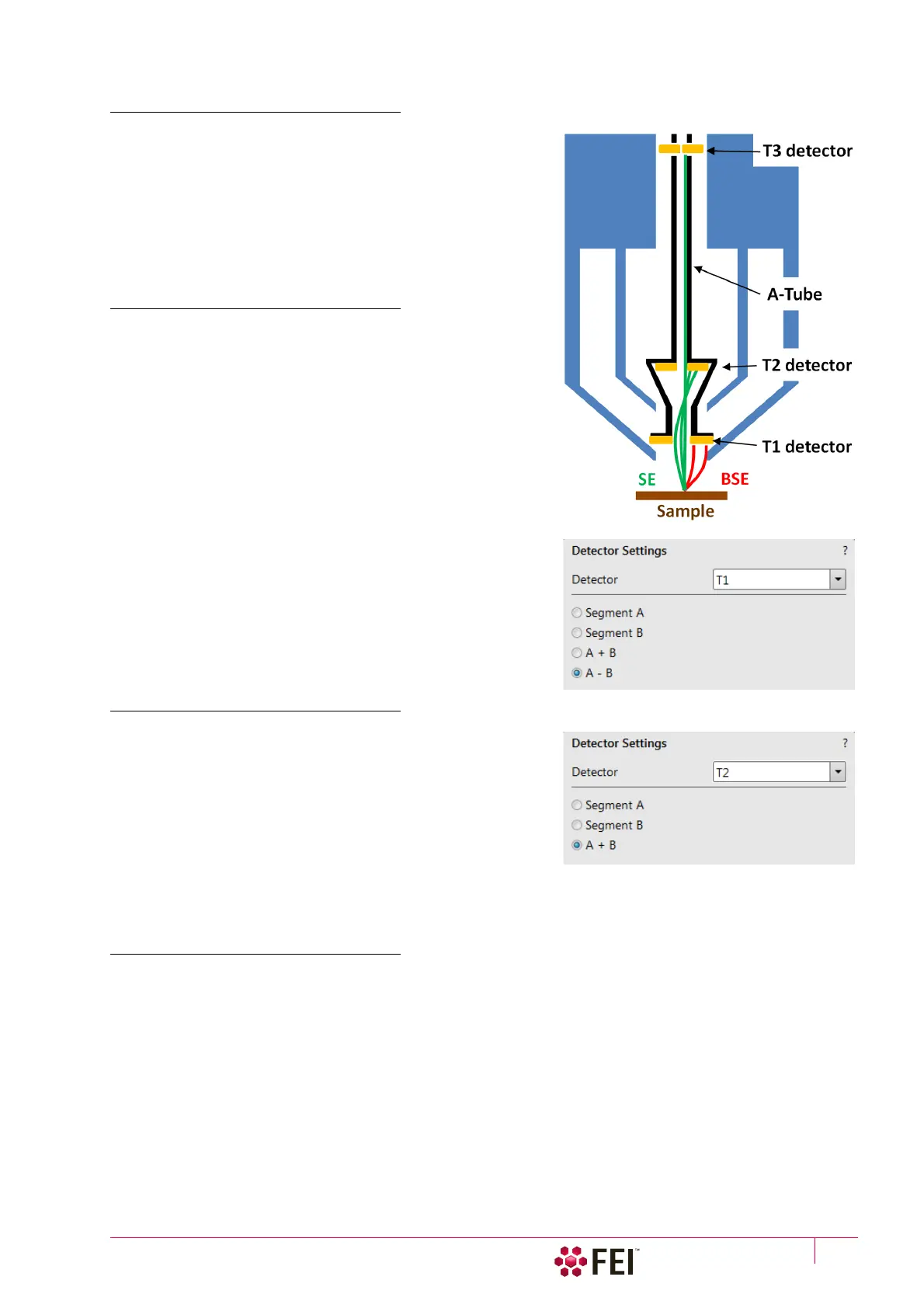
Trinity Detectors T1 / T2
Electrons generated by a primary beam can be collected by the
in-lens Trinity detectors T1 and T2, which are located inside the
final lens.
Note
Whenever the T1 or T2 is selected, the optical display is paused (the
CCD camera infra-red LED’s are switched off not to emit the photons
supersaturating the detector).
T1
The T1 detector is primarily designed to collect backscattered
electrons (BSE) and provides composite sample contrast. In the
OptiTilt and OptiPlan column Use cases, it detects backscattered
electrons through the whole range of accelerating voltages
thanks to the A-Tube at high potential that accelerates the BSE
towards the detector. In the Standard column Use case, the T1
provides strong BSE contrast at accelerating voltages of 5 kV and
higher.
Note
Use of the X-Ray Cone (see Chapter 2) blocks BSE to reach the T1
detector.
The active detector area is split into two halves and the detector
can be operated in four modes. Apart from the composite mode
A + B the detector can be operated in the topographical mode
A - B, where a pseudo-topographical imaging with suppressed
atomic number contrast and maximum topographical contrast is
obtained. Signal from each half can be also collected separately in
mode Segment A / B.
T2
The T2 detector is primarily designed to collect secondary
electrons (SE) and provides information of the sample
topography in the OptiTilt and OptiPlan column Use cases.
Thanks to the high potential of the A-Tube, the SE are accelerated
and collimated to the T2 detector. It can be operated with the
grounded A-tube as well – Standard column Use case. In this
case, backscattered electrons are collected, but the accelerating
voltage must be 5 kV at least. Intensity of the signal in the
Standard column Use case is dependent on the beam current and
working distance – the higher the beam current and shorter the WD the higher the T2 signal.
T3 (option)
Electrons generated by a primary beam can be collected by the in-column Trinity detector T3 which is located
inside the column, just below the aperture strip (see Chapter 7).