Software Control: Microscope Control Software
C O N F I D E N T I A L – FEI Limited Rights Data 3-27
Imaging Area
The Microscope Control software (UI) uses 4 independent displays for imaging samples. Each display can contain
imaging from any detector (including External and CCD), paused imaging or images loaded from a file.
Additionally, display 3 can show a mix of imaging from displays 1 and 2, and display 4 can show a mix of imaging
from display 1, 2 and 3.
There are shown either 4 displays at the same time – Quad Image mode or one display over the UI imaging area –
Single Image mode.
Each display consists of its imaging area, adjustable Databar containing the imaging parameters, selectable overlay
(user-defined coloring, annotations, measurement) and some status icons (Pause, Sample Navigation, etc.).
At any time, just one display is selected (has focus), and all functions (related to it – Pause, Sample Navigation,
image processing) applies only to imaging in this display. The selected display is marked by the highlighted (blue)
Databar and optionally also by the blue frame (see Preferences / General).
Depending on the display content and the status, some mouse functions are available over its area:
• Electron imaging (incl. External and Mix): focus, astigmatism correction, Beam Shift, magnification change
(coarse, fine), zoom (in / out), Contrast & Brightness, lens alignment, Scan / Compucentric Rotation, XY-move
(get or track mode)
• Ion imaging (incl. External and Mix): focus, astigmatism correction, Beam Shift, magnification change (coarse,
fine), zoom (in / out), Contrast & Brightness, Scan / Compucentric Rotation, XY-move (get or track mode)
• Optical imaging: 7 mm Marker placement, Compucentric Rotation, Z-move (track), Tilt
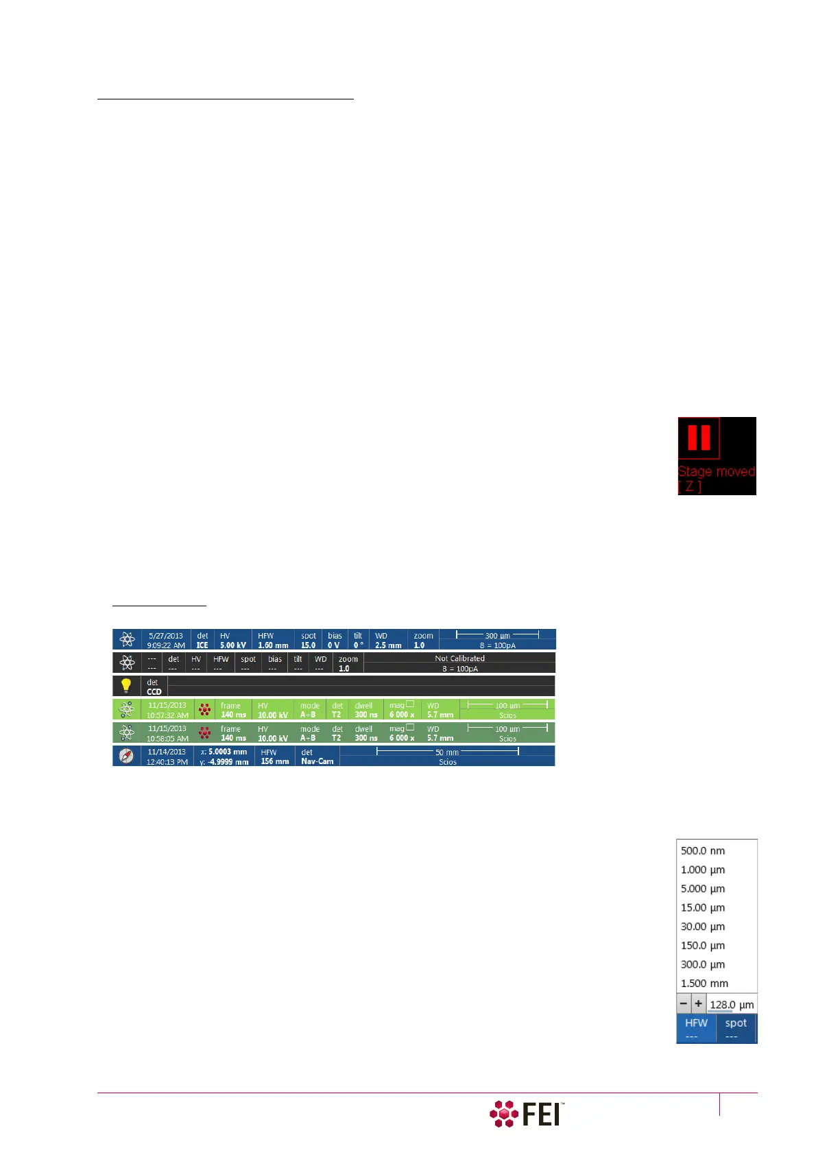
The optical imaging is automatically activated (if it is paused), when the venting procedure
starts. When it is paused and any stage movement takes place, the pause icon turns red and a
list of changed axes is shown.
Note
Due to hardware limitations, some detectors cannot be used simultaneously. They can still be selected
for different displays at the same time, but if one of them is started, the other imaging with incompatible
detectors are automatically paused.
Image Databar
Optional instrument, imaging and labelling information are shown at the base of all displays. The configuration and
available items differ for the beam selected (Electron / Ion / Optical / Nav-Cam) for the selected display.
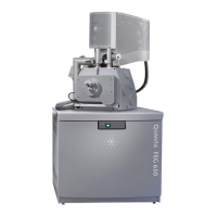
FIGURE 3-13 The Databar Examples
Note
The Databar information is always related to the actual imaging. If the imaging is paused or an image is loaded from a file,
they can differ from the actual system conditions.
Clicking on some of the image databar fields induces an active menu related to it with appropriate
choices.
Clicking on the label field induces the label editing menu.
Double-clicking on the micron bar induces the Image properties window – multiple parameters at
which an image was captured. Same functionality is caused by pressing the Shift + F1 keys.
To set information included in the databar right-click on any display databar and click on & drag
desired Available Item to the Visible Items field. Items can be placed in any order (by dragging the
item up / down within the list) and expand or contract automatically to fit the display width as
long as there is enough room, which influences all displays with the same beam.
Selected electron display
Not selected electron display
Not selected optical display
Selected Patterning display
Not selected Patterning display
Selected Nav-Cam display
(option)