Operating Procedures: Stage Control
C O N F I D E N T I A L – FEI Limited Rights Data5-32
Software Control
The Navigation page contains the Stage, Stage Z and Tilt Correction modules, which control the stage movements
that locate the position of the specimen by reference to coordinate points.
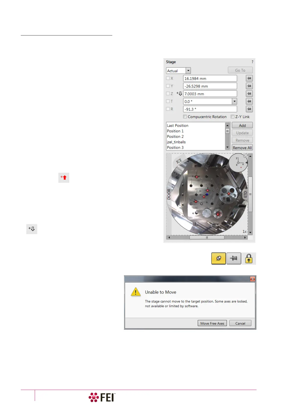
Stage module
Three modes are possible via the list box:
• Actual mode (default) – shows actual position coordinates in
the edit boxes.
• Target mode – activates when clicking on a stored position or
when editing a coordinate value.
• Relative mode – used to move stage by a given value and to
repeat it several times if needed.
Clicking on the Go To button drives the stage to a new location.
This only acts on just edited coordinates (with a tick mark).
Pressing the Enter key after editing of any coordinate value works
as the Go To button short-cut. Double-clicking on a stored
location moves the stage to the desired position immediately.
During the stage motion the Go To button changes to the Stop
button, which stops the stage immediately.
Coordinates X, Y, Z, R, T
Edit boxes for X, Y, Z, R and T coordinates are filled with the
selected or actual position values. The value changed is
automatically ticked.
Caution!
Danger of hitting the final lens! The Link Z to FWD procedure did not
pass. The red up arrow next the Z axis alerts the positive Z-axis stage
moving direction is up. It means raising a value in the Z axis edit box
causes moving the stage up towards the final lens.
After running the Link Z to FWD procedure the symbol and the
stage moving direction changes. The black down arrow next the Z
axis indicates the positive Z-axis stage moving direction is down.
The units of measure follow the Preferences / Units setting, unless
the Stage menu / User Units function is active, in which case UU is
shown for X and Y.
The software locks prevent inadvertent stage movement of selected axes during particular
applications. The edit boxes for locked axes are disabled and the stage does not move in
these directions. When any or all axes are locked the Status bar shows the closed lock
icon.
When any axis is locked and the stage
movement is required in that direction (trying
to move to the stored position), the warning
dialog appears.
When the Compucentric Rotation check box is
ticked, the R coordinate operates as the
Compucentric Rotation function (see further)
and does not physical rotate the stage.
When the Z-Y Link check box is ticked and the
stage is tilted, the system compensates for
the observed point of interest shifting during
stage move, which allows to make a Z-axis move with a tilted stage while keeping the point of interest in the field of
view. This makes it much easier when imaging with electron beam at shorter working distances to accurately reach
the beams coincidence (milling position).