Operating Procedures: Stage Control
C O N F I D E N T I A L – FEI Limited Rights Data 5-33
Location list
The Location list shows stored stage positions. When expanded the scrollbar is available. There is the Last Position
(the stage position before latest movement) in the list by default, which is updated during stage operations.
The position selected becomes the actual active position and it is highlighted in the list and also in the map area
(12).
Clicking on a position name allows a user to edit it. Pressing the Enter key or clicking on a different item confirms
the new name, pressing the Esc key restores the old name.
It is possible to load / save stage positions (stg file) with the use of File menu / Import / Export functions.
Map area
In the map area, the stage schema is represented showing all stored positions, which are listed in the Location list.
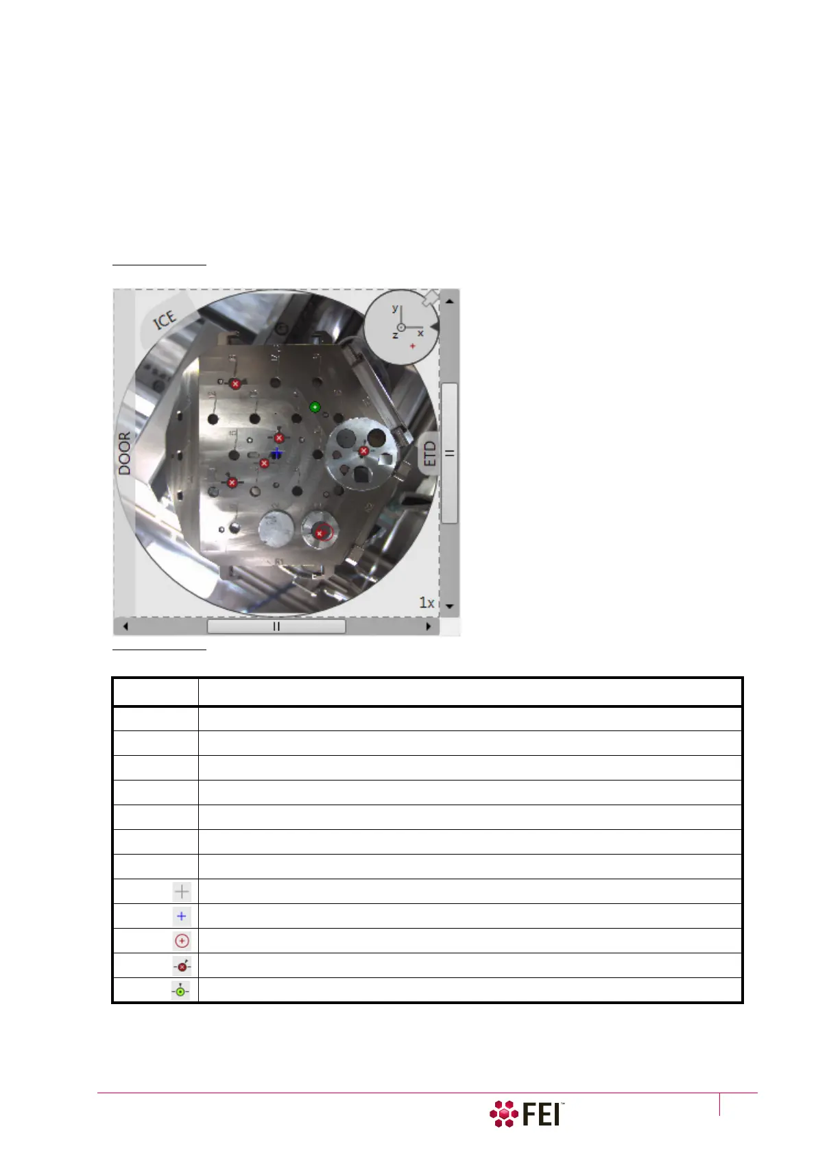
FIGURE 5-13 Map Area Elements
Double-clicking on anywhere in the circle area marks a new location (10) and moves the stage to that position.
Table 5-5:
Map Area Elements
Number Function
1. Light gray rim (dashed line): physical limit of the stage movement along the X and Y axes
2. Dark rim (continuous line): the sample holder outline
3. X / Y scroll bar: to move the map area at different magnification factors
4. Magnification factor of the map area (1× – 100×)
5. Stage rotation overlay: Chamber door / ETD / ICE / CCD camera
6. Notch (black triangle): rotation marking (active control within the Radar view)
7. Radar view X / Y / Z (perpendicular lines): stage axes
8. Gray +: mechanical stage center: X = 0, Y = 0
9. Blue +: map area center
10. Red + in a red circle / Red + (Radar view): actual stage position
11. White × on a red background: a stored location (rotation noted by the black triangle)
12. Black on a green background: a stored position selected (highlighted in the location list)