Triggered
waveform----------tl •
-l'L
h
Trigger 1 v 1
\J
Signal i 1
tU
n,-_
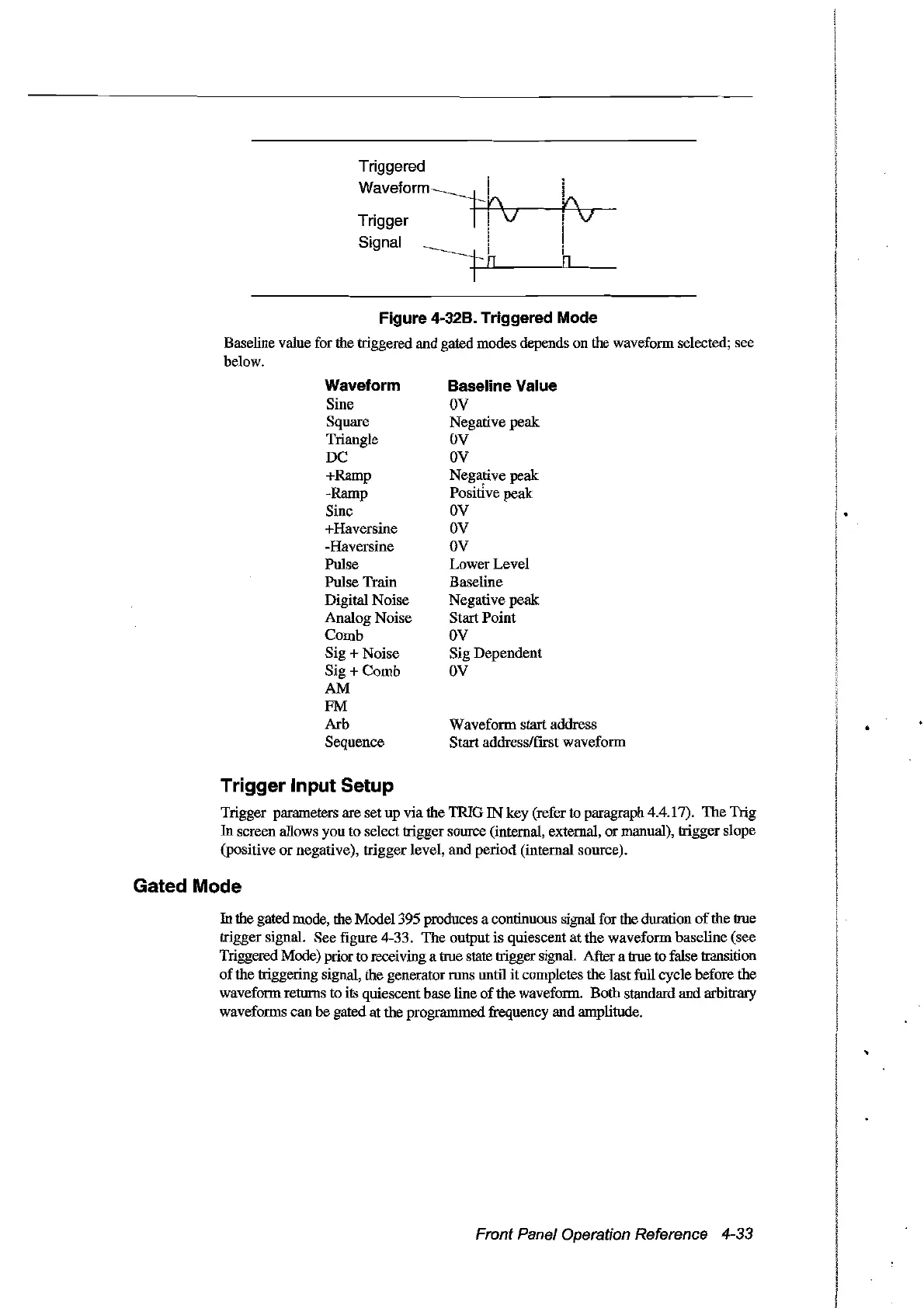
Figure 4-32B. Triggered Mode
Baseline value for the triggered and gated modes depends
on
the waveform selected; see
below.
Waveform
Sine
Square
Triangle
DC
+Ramp
-Ramp
Sinc
+Haversine
-Haversine
Pulse
Pulse
Train
Digital
Noise
Analog
Noise
Comb
Sig +
Noise
Sig +
Comb
AM
FM
Arb
Sequence
Baseline Value
OV
Negative
peak
DV
DV
Negative peak
Positive peak:
DV
DV
DV
LowerLevel
Baseline
Negative
peak
StartPoint
DV
Sig
Dependent
DV
Waveform startaddress
Start address/first waveform
Trigger Input Setup
Trigger parameters are set
up
via
the
1RIG
IN
key (refer to paragraph 4.4.17).
The
Trig
In
screen allows you
to
selecttrigger source (internal, external,
or
manual), trigger sIope
(positive
or
negative),
trigger
IeveI,
and
period
(internaI source).
Gated Mode
In the gated mode, the Modei 395 produces a continuous signal for the duration
of
the true
trigger signal. See figure 4-33.
The
output is quiescent
at
the
waveform baseline (see
Triggered Mode) prior to receiving a true state trigger signal. After a true to false transition
of
the triggering signal, the generator
mns
until
it
completes the last full cyclebefore
the
waveformreturns
to
its quiescent base line
of
the
waveform. Both standard
and
arbitrary
waveforms
can
be
gated
at
the prograrnmed frequency and amplitude.
Front Panel Operation Reference 4-33
Artisan Technology Group - Quality Instrumentation ... Guaranteed | (888) 88-SOURCE | www.artisantg.com