4.4.12.17 Signal Plus Comb
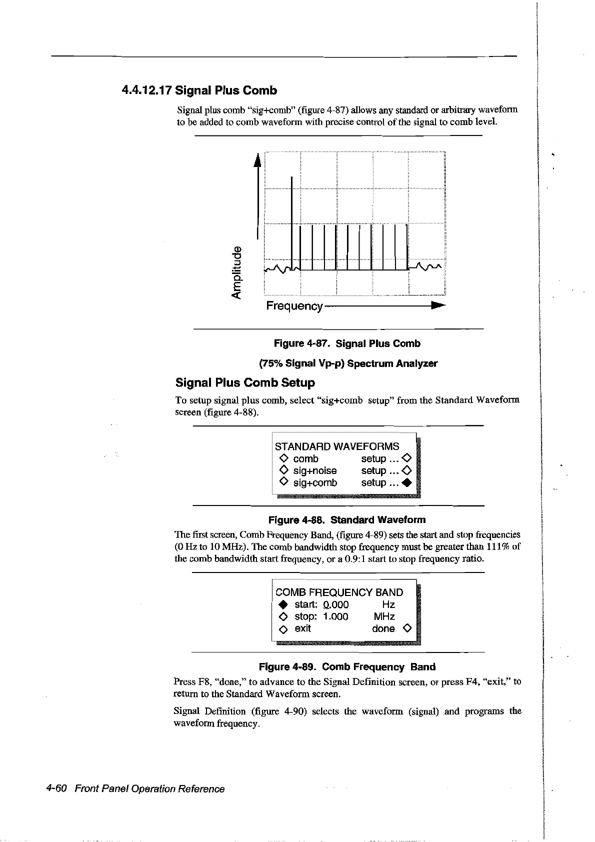
Signal plus comb "sig+comb" (figure 4-87) allows any standard or arbitrary wavefonn
to be added to comb waveform with precise control
of
the signal to comb level.
Q)
"0
::s
:!:::
a.
E
«
J
,....................
r-'\rl
....
1
li
~
i
Frequency--------------~~
..
Figure 4-87. Signal Plus Comb
(75% Signal Vp-p) Spectrum Analyzer
Signal Plus Comb Setup
To setup signal
plus
comb, select "sig+comb setup" from the Standard Waveform
screen (figure 4-88).
STANDARD WAVEFORMS
o comb setup 0
<>
sig+noise setup
<>
o sig+comb setup .
Figure 4-88. Standard Waveform
The first screen, Comb Frequency Band, (figure 4-89) sets the start and stop frequencies
(0
Hz
to 10 MHz). The comb bandwidth stop frequency must he greaterthan 111%
of
the comb bandwidth startfrequency, or a 0.9:1 start to stop frequency ratio.
COMB FREQUENCY BAND
• start:
0..000
Hz
o stop: 1.000 MHz
o exit done 0
Figure 4-89. Comb Frequency Band
Press F8, "done," to advance to the Signal Definition screen,
or
press
F4,
"exit," to
return to the Standard Waveform screen.
Signal Definition (figure 4-90) selects the waveform (signal)
and
programs the
wavefonn frequency.
4-60 Front Panel Operation Reference
Artisan Technology Group - Quality Instrumentation ... Guaranteed | (888) 88-SOURCE | www.artisantg.com