Step 5 Viewing the
AM
Signal
Connect the scope and
Model395
as described in paragraph 3.5. Setup the external
signal generator to 2 kHz, 1.25 Vp-p sine wave. Connect an external signal generator's
Function Output to the to the Model
395's
AM
IN connector.
Be
sure to properly
tenninate the external signal generator's Function Output.
Also
try
to create the
AM
signal using the
ModeI395's
internaI
AM
wavefonn.
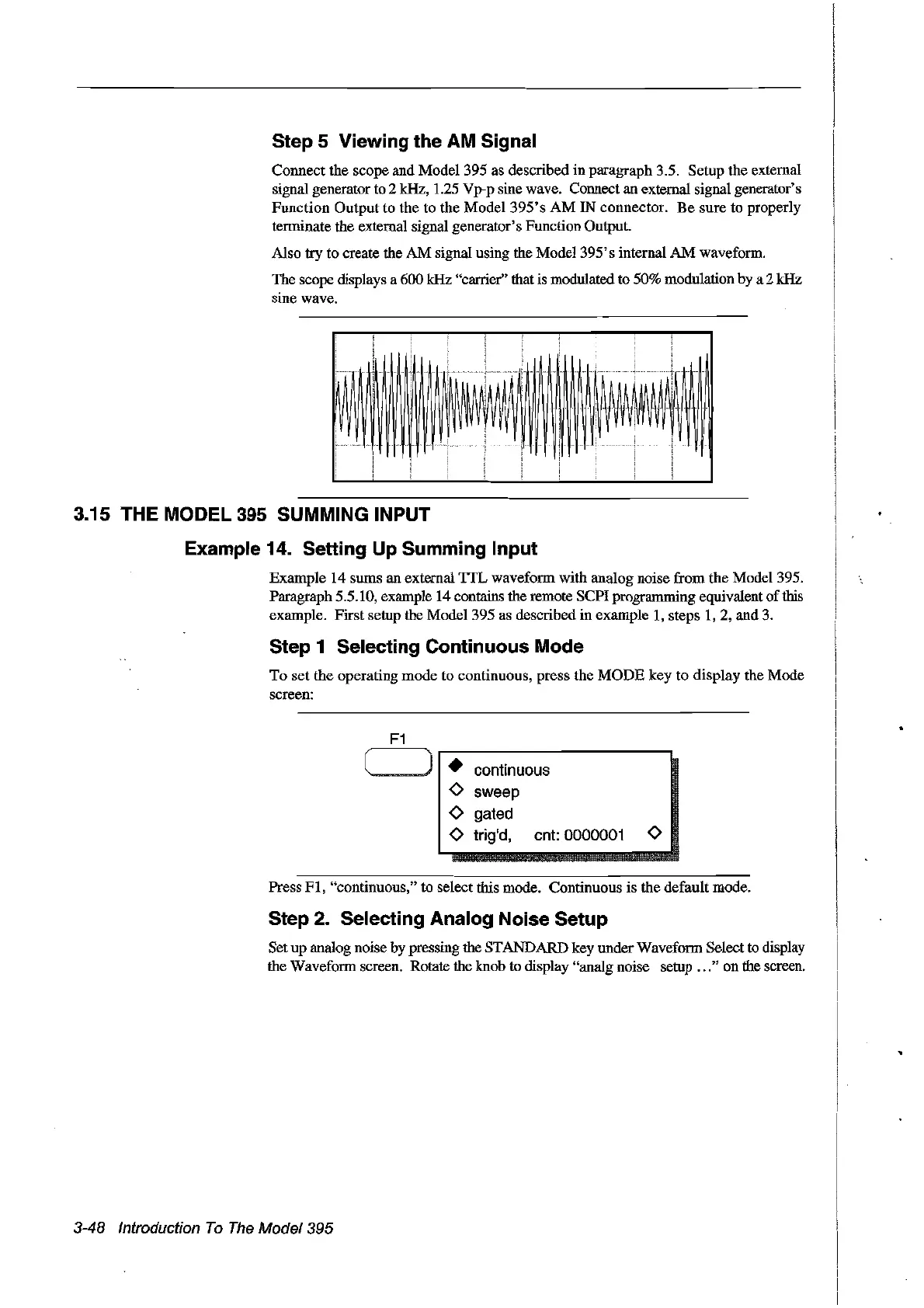
The scope displays a 600 kHz "carrier" that is modulated to 50% modulation by a 2 kHz
sine wave.
p
HH
IH
~!~
~
i
!W~
~
Un
H
..........
3.15 THE
MODEl
395 SUMMING INPUT
Example 14. Setting Up Summing Input
Example 14 sums an external
TIL
wavefonn with analog noise from the Mode1395.
Paragraph 5.5.10, example 14 contains the remote SCPI progranuning equivalent ofthis
example. First setup the Model 395 as described in example
1,
steps
1,
2, and
3.
Step 1 Selecting Continuous Mode
To
set the operating mode to eontinuous, press the
MODE
key to display the Mode
sereen:
•
continuous
0
sweep
0
gated
0
trig'd,
cnt: 0000001
0
Press
FI,
"continuous," to select this mode. Continuous is the default mode.
Step 2. Selecting Analog Noise Setup
Set up analog noise by pressing the STANDARD key under Waveform Selectto display
the Wavefonn screen. Rotate the knob to display "analg noise setup
...
" on the sereeil.
3-48 Introduction
Ta
The
Madel 395
Artisan Technology Group - Quality Instrumentation ... Guaranteed | (888) 88-SOURCE | www.artisantg.com